
Instructions
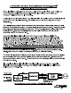
Table Of Contents

RONK ELECTRICAL INDUSTRIES, INC. PH: (217) 563-8333 MAN3081
ADD-A-PHASE
®
TYPE HE-AA/AA-HE
DESCRIPTION OF OPERATING CHARACTERISTICS
The Automatic Adjusting ADD-A-PHASE is designed to handle the unique operating characteristics of
hydraulic pump motors. The Type HE-AA is for hydraulic elevator applications, and the Type AA-HE
is for hydraulic balers and compactors. The hydraulic pumps used in these applications generally put
their motors under variable loads. These converters have an automatic adjusting circuit board which
senses load and adjusts the current output (for better current balance to the motor) under these
varying load conditions.
CONVERTER OPERATION
STARTING THE MOTOR
– A start contactor brings in a set of electrolytic type capacitors that supply
the “manufactured” (“A”) phase’s starting current, which accelerates the motor to its operating speed.
1. A current transformer (C.T.) is used (on the “C” phase) to detect current being drawn by the
motor. Recognition of this condition by the Auto Adjust circuit board initiates the converter’s
motor start sequence. The auxiliary relay closes. Its closing makes the start contactor close.
This connects a bank of start (electrolytic) capacitors to the motor, developing the starting
current needed to accelerate the motor.
2. The duration of the start sequence is normally very short, two seconds or less. A voltage
sensing relay (control relay) will sense a rise in the A-C phase voltage. This rise will occur as
the motor comes to speed. The control relay will de-energize the start contactor. This
removes the start capacitors from the circuit.
RUNNING THE MOTOR
– The autotransformer and run capacitors develop running current for the
“A” phase. Changing the capacitance or the taps on the autotransformer will change the currents to
the motor. See the Balancing instructions for further information on balancing. Note: Most AA units
do not require balancing.
1. Two banks of run capacitors provide running current to the motor for the (“A”) phase. The
main bank is always connected and supplies the normal operating current. The run assist
bank is connected through a contactor controlled by the Auto Adjust circuit board. It is brought
into the circuit during motor starts and when high load conditions exist. The number of
capacitors connected and the MFD rating of the capacitors determines the manufactured
phase’s current output to the motor. Capacitors for the 208 and 240 V output units are
connected in parallel, while the 480 V output units are series pairs connected in parallel.
2. Some motors, depending on their power factor (P.F.) may require changing to a different tap of
the autotransformer to achieve better current balance among the three phases.
RUN ASSIST
– The Auto Adjust circuit board, unique to the Automatic Adjust ADD-A-PHASE units,
constantly monitors the operating load on the motor (by detecting the amperage on the “C” phase).
When the board senses a significant increase in motor load, additional run capacitance is added to