Instructions and Operating Manual SERIES X90 POINT LEVEL MONITORS POINT LEVEL MONITORS SERIES X90 Instructions and Operating Manual Customer’s Name ____________________ Customer’s P.O. No. __________________ Ronan Job No.
TABLE OF CONTENTS 1.0 2.0 3.0 4.0 4.1 4.2 4.3 5.0 5.1 6.0 7.0 7.1 7.2 7.3 8.0 9.0 9.1 9.2 9.3 9.4 10.0 11.0 11.1 11.2 11.3 11.4 11.5 11.6 11.7 11.8 11.9 11.10 12.0 12.1 12.2 13.0 General Description ......................................................................................................... Specifications (Standard) ................................................................................................. Theory of Operation ..............................................................
1.0 GENERAL DESCRIPTION The Ronan Series X90 Point Level Monitor economically and reliably solves many process problems in which noise, temperature, abrasive or corrosive conditions preclude the effective utilization of sonic, capacitative, float or other techniques. This is a non-contact system. Normally, a small Cesium-137 radioisotope source is housed in a lead-filled shielding enclosure known as the source holder.
Time Delay Range: Integral: 0.5 to 20 seconds (10 or 20 seconds normal); jumper-selectable Remote: .05 to 20 seconds (10 or 20 seconds normal); jumperselectable Display: Integral: LED status indicator Remote: LED status indicator Accuracy: Integral ± 1/8” Remote: ± 1/8” All equipment approved by CSA. ————————————————————————— 3.
the tube output does not indicate a minimum background value (due to a malfunction in the G-M tube or its power supply) the process (and failure, if used) relay automatically changes over, indicating an alarm condition. The failure alarm will occur anytime the output from the tube is zero. ————————————————————————— 5.0 TIME DELAY OPTIONS The basic time constant is 0.5 seconds to 40 seconds, depending upon the span setting. Additional time delays available are 0.1, 5, 10 and 20 seconds.
module is not necessary in order to change wiring. Grommeted holes are provided on the top and bottom surfaces of the chassis for cable entry and exit. Overall dimensions are 7.25” high X 4.5” wide X 5.75” deep (18.42 cm X 11.43 cm X 14.6 cm). Refer to drawing number C-1359-K for terminal designations for power wiring and hook-up to the remote probe driver board. 7.3 Integral Model X90-1005 Refer to drawing A-1697-K for rear-panel input power wiring connections and relay contact wiring connections.
10.0 TROUBLESHOOTING The X90 is constructed to require the minimum of maintenance. Operated properly, it should not require any maintenance for a considerable period of time. Any necessary troubleshooting should start with the power supplies. Ronan Engineering suggests that a voltmeter with a resistance of at least 20 kohm/V be used for measurement of voltages. Verify that the power supplies are working before starting with the rest of the circuitry.
In the majority of Ronan installations, the source is contained in a lead-filled source holder with an ON/OFF mechanism. The holder is designed so that the radiation field is 5 mR/hr or less at a distance of 12 inches from the surface of the holder when is is in the OFF position. When the source holder is mounted on the pipe or vessel and turned to the ON position, the pipe walls, process material and mounting bracket absorb most of the radiation. Again, the field intensity is about 5 Mr.
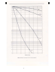
Figure 2: Radiation Transmission CS-137 for Various Materials 9
Calculate the radiation field intensity at 12 inches from the surface of the vessel shown in Figure 3. Total distance = 12 + 2 + 10 = 24 inches Dose rate for unshielded source: Dose rate = 0.5 X 10 (24)2 X 1000 = 5 476 X 1000 = 8.6 mr/hr a) The “Individual User” listed on the “Application for By-product Material License” (Form NRC-313) is responsible for the source.
f) The area in the vicinity of the source must be posted with a radiation warning sign, if the radiation field is greater than 5 mr/hr at a distance of 12 inches from the surface of the gage. [20.204a and 20.203] g) Personnel monitoring is required when personnel are apt to receive a dose in excess of 23 mrem/wk or when they enter a radiation field greater than 100 mr/hr. [20.202a] h) Whenever the source is to be discarded, it must be returned to Ronan Engineering for proper disposal.
After these preliminary services are performed, a person specifically licensed by the NRC or an agreement state must do the start-up of the gage. This involves unlocking the source holder and turning it ON; testing for proper operation of the source holder and position indicator; making the initial radiation field intensity survey; and initial testing for leakage of radioactive material.
Figure 5: Wiping the Test Points (Well Sources) 11.9 Standard Sources SA-1, SA-8 11.9.1 ON/OFF mechanism: To test the ON/OFF mechanism, move the handle back and forth several times between the ON and a OFF positions. The handle should always move freely. There may be some slight resistance to movement due to bearing friction. Do not force the handle. If a portable radiation survey meter is available, the radiation field intensity can be measured at points around the detector housing. 11.9.
12.0 LEAK TEST PROCEDURES FOR SEALED SOURCES materials, issue a report based on the results and forward a copy of the results to the customer immediately. 12.2 Using the Leak Test Kit: 12.1 Ronan Leak Testing Service The NRC requires that all sealed sources be tested for leakage at specified intervals. Only Kr-85, tritium and certain sources of very small activity (10 CFR 30.18a) are exempted from leak testing. Ronan Engineering provides for users’ convenience and safety the “Leak Testing Service.
PARTS LIST—SERIES X90 POINT LEVEL MONITOR X90-1004 or X90-1004X Probe (continued) Item Qty. ID Part No.
PARTS LIST—SERIES X90 POINT LEVEL MONITOR X90-301(V) (continued) Item Qty. ID Part No. Description Vendor 23 24 25 26 27 28 29 30 31 32 33 3 2 3 2 2 5 1 1 2 2 R27,33,34 R29,30 R31,32,35 C1,2 C3,4 C4,7,8,9,10 C6 C11 C12,13 C14,15 Resistor, Carbon, ¼ W, 5%, 100 k Resistor, Carbon, ¼ W, 5%, 150 k Resistor, Carbon, ¼ W, 5%, 680 Capacitor, .001 mfd/1 kV Capacitor, Met. Polycarb., .47 mfd/630 V Capacitor, Met. Polyester, .1 mfd Capacitor, 220 pFd Capacitor, Met. Polycarb., .
PARTS LIST—SERIES X90 POINT LEVEL MONITOR X90-301(V) (continued) Item Qty. 63 2 ID Part No. Description Vendor Relay Holdown Potter & Brumfield 1598-102 Test Jack, Red H.H. Smith 1598-103 Test Jack, Black H.H. Smith Nuts for Test Jacks Tinnerman HLMP-0103 Mounting Clip and Ring, LED H.P. X90-301 Transformer MCI Ltd.
PARTS LIST—SERIES X90 POINT LEVEL MONITOR X90-1005 (continued) Item Qty. ID Part No. Description Vendor 20 1 R23 RN55C1001 Resistor, M.F., ¼ W, 1%, 1 k Mepco 21 1 R25 RN55C7502 Resistor, M.F., ¼ W, 1%, 75 k Mepco 22 1 R26 68WR10K Trim Potentiometer, Cermet 10 k Beckman 24 3 R27,33,34 RC07GF104J Resistor, Carbon, ¼ W, 5%, 100 k A.B. 25 2 R29,30 RC07GF155J Resistor, Carbon, ¼ W, 5%, 150 k A.B. 26 3 R31,32,35 RC07GF680J Resistor, Carbon, ¼ W, 5%, 680 A.B.
PARTS LIST—SERIES X90 POINT LEVEL MONITOR X90-1005 (continued) Item Qty. ID Part No. Description Vendor 64 1 IC2 7906C Voltage Regulator, 6 V Motorola 65 1 IC3 MC14001B Quad 2” NOR Gate Motorola 66 1 IC4 NE555N 555 Timer Signetics 67 1 IC5 DS3634N Driver National 68 1 IC6 DS3633N Driver National 69 2 RY1,2 K10P11D15 Relay, 4 PDT, 24 Vdc 70 2 Relay Socket 71 2 Relay Holdown 72 1598-102 Test Jack, Red Potter & Brumfield Potter & Brumfield Potter & Brumfield H.