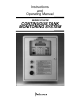
Instructions and Operating Manual SERIES X76CTM CONTINUOUS TANK MONITORING SYSTEM
TABLE OF CONTENTS 1.0 Introduction . . . . . . . . . . . . . . . . . . . . . . . . . . . . . . . . . . . . . . . . . . . . . . . . . . . . . . . . . . . . . . . . 3 2.0 General Description . . . . . . . . . . . . . . . . . . . . . . . . . . . . . . . . . . . . . . . . . . . . . . . . . . . . . . . . . . 3 3.0 Safety Rules . . . . . . . . . . . . . . . . . . . . . . . . . . . . . . . . . . . . . . . . . . . . . . . . . . . . . . . . . . . . . . . . 3 3.1 Intrinsic Safety . . . . . . . . . . . . . . . .
TABLE OF CONTENTS (CONT.) 12.0 Drawing (Cont.) Tank Leak Sensors, Models LS-3, LS-3s, and LS-3ss . . . . . . . . . . . . . . . . . . . . . . . . . . . . . . . . . 30 Tank Leak Sensors, Models LS-7 and LS-7s . . . . . . . . . . . . . . . . . . . . . . . . . . . . . . . . . . . . . . . . 31 Tank Leak Sensor, Model LS-30 . . . . . . . . . . . . . . . . . . . . . . . . . . . . . . . . . . . . . . . . . . . . . . . . . 32 Tank Leak Sensors, Models JT-2P and JT-2V . . . . . . . . . . . . . . . . . . . . . .
1.0 INTRODUCTION 3.0 SAFETY RULES The X76CTM Continuous Electronic Tank Monitoring System is designed to tighten inventory control of fuels and other liquids stored in underground and aboveground tanks. The probe, controller and sensors form a system that measures fuel height, fuel temperature, water height, and leakage. It will also provide information on gross and net fuel volume, leak alarms, and time and date of the leak.
and operating this product according to the instructions and warnings that follow. Failure to do so could create danger to life and property and result in voiding all warranties connected with this product. production quality equipment and inspection of manufacturing and quality control facilities.
3. Locate the intrinsic safety barrier cover inside the controller cabinet and remove the screws; open the cover. 1. Warranty & Checkout Forms. 2. Tank specifications including tank material, volume, diameter, and Manufacturer Height to Volume Conversion Chart. a) Locate the power supply terminals and verify that an earth ground has been provided, using a #12 AWG wire. 3. Tank tilt information (if the tank is tilted). 4.
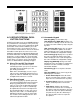
Figure 1: Keypad Push-button Layout. 4.0 KEYPAD EXTERNAL PUSHBUTTON FUNCTIONS 4.3 Commands Keypad Enter Key [ENT]. Used for data entry. Tank Number Key [TANK NO]. Prompts user to select tanks 1 through 8. It can also be used to advance the tank number by depressing the key twice. A TEST push button and a green POWER indicator are provided in the external layer of the panel. Any incoming alarms can be silenced through the TEST push button.
4. Daily Sales Report. Prints the amount of product sold per tank for the last 24 hours (from midnight to midnight) and includes the number of days of available inventory at current usage rate. nal Identification Number (PIN) for the other users. Any user can change their own PIN at any time. The procedure for changing the PIN is described in Section 10. When the X76CTM is in one of the default displays, press any key (0-9) to identify the user to be logged in.
MNO PRS TUV YZl Assigned Assigned Assigned Assigned on on on on 5 6 7 8 4. Configure initial product levels. 5. Configure tank-based alarms: low, low-low, high, high-high and maximum water level alarm. Configuration of the station’s name and address, the contacts, relays, the annunciator, and the product information is order independent and can be done at any time. Press the [TANK NO] key to toggle letter case. 7.
. 96, Station City the times, the time is cleared and assumed not to be used for filtering. If the event is tank specific, a prompt for selecting the tank will be displayed (some events like contact, login, and logout are not tank related). After selecting the filter, the filtered events will be browsed the same as F100. Sets the stations city, state and zip code. Station City Woodland Hills CA 91367 Function Description 43 44 45 46 10.
. 46, Date & Time Format [HI, LO] The X76CTM displays the following strap chart table.
7. Enter the dipstick level at the probe opening. iWARNING: The tank parameters are changed using Function 74. For the tank diameter, the length of the probe will automatically recalculate to reflect the new diameter. If the probe length is not matched with the recalculated length, it must be changed again. 8. Enter the dipstick level at the fill opening. . 45, Select Probe Type Use this function to select the type of the probe, and also to set up the probe parameters.
Enter product expansion 0.00065 Enter coefficient of expansion and press [ENT.]. Function 92 is used when the product name cannot be found in product codes. The coefficient can be viewed or changed with this function. It is not necessary to enter the decimal point. during transfer is not considered as delivery. To minimize confusion, the user can set up a value that will eliminate the small levels. The default threshold is 200 gallons. Use Function 43 to change the delivery threshold and press [ENT.
. 68, Manifolds to t# 12345678 be conducted. The higher it is, the easier it is to enter a leak test, but the data could be noisier and the results incorrect. The X76CTM allows for the combining of two or more tanks to generate the combined product volume of physically manifolded tanks. If tank 2 is manifolded to tank 1, the reports for tank 1 will contain the manifolded volumes, while those for tank 2 will not. The same applies to the leak test.
Edit the relay name, and press [ENT.]. (By default, the relays are named RELAY1-4). Leak Detected. This event is made active when a test with a maximal duration was ended, the probability of leak detection is higher than 95%, and the leak detected was higher than the threshold (typically 0.2 gph). Enter relay name Relay 1 Enter the relay time-out (0-255 s), and press [ENT.]. Entering 0 means that there is no time-out.
. 62, Enter Current Code For: Setup contact (HI,LO)_1 Input01 Use [HI] and [LO] keys to scroll through the available contact listings. Press [ENT.] at the selected contact and start editing. Enter contact name: Contact01 To make a change to the PIN code, use Function 62. For security purposes, the X76CTM is designed so that only the administrator can change user codes. To change the code of another user, the administrator must first log in. At the default display, press the user number to be changed.
. 100, Browse Events This function is used for unconditional and unfiltered display of the events from the event log, always beginning with the most recent event. To browse the event history, use Function 100. This display defaults to the last event. To scroll through the list of events use the [HI] and [LO] keys. Pressing the [PRINT] key prompts the X76CTM to print the event that is on the screen. If [PRINT] is pressed again, the next 20 events will be printed.
9. Contacts Settings. Prints the contact settings: type (normally open/normally closed), current state alarm/ normal), and the relay to be activated depending on the Report 3: Shift Report. Report 4: Daily Sales Report. Report 5: CSLD Report.
prints the settings for all contacts, including the level gauge probe inputs. Ronan Engineering LDM 21200 Oxnard Street Woodland Hills CA 91367 10. Relays Settings. Prints the current settings for the 76CTM relays.
normally closed), current state (alarm/normal), and the relay to be activated depending on the contact state. This report prints the settings for all contacts, including the level gauge probe inputs. 10. Relays Settings. Prints the current settings for the 76CTM relays. For each relay (total of 4 relays) the current state, logic (normally open/normally closed) and the time-out is reported. If the time-out is 0, the relay will stay in this state until changed.
system will prompt again for the new user 4 PIN number. Enter the new code. trator can access and alter the user codes. Function 62 is used to change the PIN codes. During new code entry, the numbers are substituted with asterisks (*) on the display for additional security. The administrator should first log in, then enter the new user number. This starts the login procedure for the new user. When Function 62 is pressed, a prompt for entering the user’s PIN will appear. 10.
factory for other material types). Float Material: Ceon-D, X95040XB; 316SS, 95140XB. Repeatability: .02% or full range. Accuracy: .05% of full range. Resolution: ± .001 in. Site Characteristics: 4 in. schedule 40 riser. Wiring: Two (2) conductor shielded cables, max. length 2500 ft. Approvals: UL Listed 48RO, intrinsically safe for use in hazardous locations, Class I, Div. 1, Groups C & D; Class II, Div. 1, Groups E, F, & G; Class III, Div. 1. support the floating point format.
Switch: Type: DPDT, N.C. top, N.O. bottom. Rating: 10 VA. Float Material: Polysulfone. Pressure: 50 psi maximum. Leads: 20 AWG. Application: Vertical position high/low level. detection, 4 in. separation. Approvals: UL Listed 48RO. Classification: Class I, Groups A, B, C, and D; Class II, Groups E, F, and G. Switch: Type: SPDT, N.O. (shelf condition). Rating: 10 VA. Electrical Connection: ½ in. NPT with PVC insulated 18 AWG color coded leads. Pressure: Connection: ¼ in. NPT.
TO MODEM KIT POWER LIGHT FROM DOOR OF ENCLOSURE PRINTER CABLE DWG. X76B470-2 RED BLK RED TEST SWITCH RED BLK FROM DOOR OF ENCLOSURE DISPLAY CABLE DWG. X76B470-2 J4 BLK J2 BLU HORN BLK V- 5 4 3 2 1 C L L L L O XX X X M 1 2 3 4 18 AWG. 14 J5 1 1 J6 J3 XIN2 XIN1 COM 2 3 4 5 AUX3 AUX2 #6 RING RUGS TYP. 23 GRN BLK WHT 25 SEE MODEM CABLE ASSEMBLY DWG. X76C668 7 3 2 AUX4 RECEPTACLE BOTTOM VIEW 1 18 AWG.
0.312” Dia. (7.67 mm) 4 Plcs. A 5.625” Dia. (142.88 mm) 11 13 20 38 37 6 43 33 14 DATA DISPLAY MODULE P R O G R U N 7 4 1 C CE 8 5 2 0 15 39 32 COMMANDS DATA ENTRY ALARM/TEST 3 39 44 9 6 3 44 1 4 19 39 17 44 18 13.500” (342.90 mm) 15.500” (397.70 mm) 16 25 27 29 24 26 28 7 12 A 1.000” (25.40 mm) 8.000” (203.00 mm) 33 SECT A-A 22 23 10 37 12.000” (304.80 mm) 43 8 31 34 35 MODEM PORT (COM 1) SERIAL PORT (COM 2) 9 AC POWER INPUT AUX. OUTPUT I.S.
Item Model No. Description Item Model No. Description X76D640-1 X76D640-2 X76D640-3 X76CTM-1 Assembly (115 Vac) X76CTM-2 Assembly (220 Vac) X76CTM-3 Assembly (115 Vac with Modem) X76CTM-4 Assembly (220 Vac with Modem) 28 31-968.2.2 LED, Red 29 31-968.2.5 LED, Green 30 ST-2 Hub 31 94F720 Weathertight Connector Cap 32 PKT-14.
NON-HAZARDOUS HAZARDOUS MANHOLE GROUND LEVEL CABLE GRIP PROBE WIRE OUTSIDE WALL SERIES X76CTM-4X CABLE GRIP 950 CAP WATERPROOF JUNCTION BOX (SEE DETAIL A) 950 4" TOP SEAL ADAPTOR PROBE CODE REP. RATE/SPEED OF WIRE VAPOR SEAL 16" MIN.
HAZARDOUS LOCATION NON HAZARDOUS LOCATION SEALED JUNCTION BOX FOR WIRING DETAILS SEE DRW. X76D474-1 + WHITE _ BLACK G + _ 1 SHIELDED CABLE (SEE CABLE NOTE) + TO ADDITIONAL PROBES AS REQUIRED WIRE IDENTICAL AS ABOVE APPROVED SEAL IE: EXPLOSION PROOF CONDUIT SEAL _ RELAY #3 + _ 950xxxB OR 951xxxB PROBE U.L. LISTED INSTRINSICALLY SAFE FOR USE IN HAZARDOUS LOCATIONS CLASS I, DIV. 1, GRPS. C & D; CLASS II, DIV. 1, GRPS. E, F & G; CLASS III, DIV. 1 2 FOR WIRING DETAILS SEE DRW.
11.00” PIN 1 TO MODEM KIT 6 5 4 3 PART NUMBER PIN 1 TO J1 CONTROLLER BOARD COM 1 PIN 1 1.00” TYP. ± .50 BOTH 1 1 ENDS MODEM PORT COM 1 2 13.00” DE9P 1 2 3 5 DB25S 1 2 3 7 BROWN BLACK Modem Cable Assembly BLUE 7282-6SG-300 SHIELD BLACK BROWN 1 2 3 4 5 BLUE Item 1 2 3 4 5 6 Model No.
9 PIN CONNECTOR CABLE ASSEMBLY 4 5 2 3 1 NOTE: Cable length per customer order. Maximum length 25 ft. HOST DE9S X76CTM 6282-6PG-3XX 2 2 3 3 5 5 9 Pin Cable Assembly Item 1 2 3 4 5 NU Model No.
BLACK RED 3/4 NPT CONNECTION .875 in. 3.000 in. SWITCH FLOAT ® LISTED 48RO 1.310 in. INSTALLATION INSTRUCTIONS FOR STEEL DOUBLE WALL TANKS Lower sensor on cable until it rests on bottom of tank annulus in a vertical position. Pull the remaining cable into the junction box and cut off the excess length. Secure cable to prevent slipping into the tank annulus. Connect leads to wire from the tank monitor input terminal strip.
FLOAT INTERNAL SWITCH 0.125 in. WIRE 1.500 in. 0.125 in. 2.376 in. 0.375 in. ® INSTALLATION INSTRUCTIONS FOR FIBERGLASS TANKS LISTED 48RO 1. Insert fish tape through annulus space. 2. Attach pull-string to LS-7 (LS-7s). 3. Tag signal cable and pull string each 18 feet from LS-7 (LS-7s). Typical for 8 foot diameter tank. 4. Attach fish tape to pull string. WIRE INSTALLATION CABLE 5. Pull LS-7 (LS-7s) through tank annulus. 6. Match tag mark on signal cable and pull string. 7.
GREEN WHITE BLACK RED 1/2 NPT CONNECTION 0.875 in. ® SWITCH LISTED 48RO FLOAT TO CONTROL PANEL RISER CAP 7.750 in. RISER RESERVOIR INTERSTICE LIQUID TANK WALL TYPICAL LS-30 POSITIONING FLOAT 1.310 in. INSTALLATION INSTRUCTIONS LS-30 FOR DOUBLE WALL FIBERGLASS TANKS WITH INTEGRAL RESERVOIR Lower sensor on cable until half* of sensor is submerged in liquid. Pull remaining cable into junction box and cut off excess cable length. Secure cable to prevent slipping into tank annulus.
RED (CAPPED WIRE) GREEN GREEN GREEN 1/2 in. NPT ELECTRICAL CONNECTION ® LISTED 48RO PRESSURE SWITCH RELIEF VALVE 6.25 in. 5.00 in. 1 in. MALE NPT INSTALLATION INSTRUCTIONS Install the JT-2P Positive Pressure Leak Sensor or JT-2V Positive Vacuum Leak Sensor on the tank interstice riser. All other tank ports must be sealed with #150 class pipe fittings. Teflon paste type sealer is suggested for all threaded joints.
PRINTER REPLACEMENT AND PAPER REPLACEMENT INSTRUCTIONS Ribbon Replacement. 1. Loosen captive screws to access printer ribbon. 2. Gently pull printer ribbon upward. 3. When reinstalling ribbon, it is important that the ribbon itself be lined up between the print head and the impact plate. Paper Replacement. 1. Remove paper roll from spindle. 2. Place new paper roll on spindle. 3. Gently feed paper into the feed slot while depressing the feed button, until paper begins to feed through. 4.
CHECKOUT FORM, PART 1 Serial Number _________________ Installation Location Installed By Distributor Date ______________________________________________ Date ______________________________________________ Facility Name _______________________________________ Street _____________________________________________ Facility Name _______________________________________ Street _____________________________________________ Date ______________________________________________ Facility Name __________________
WARRANTY REGISTRATION FORM, PART 2 WARNING! Failure to return the Warranty Registration Form will void any and all WARRANTY CLAIMS. Installing (Company) _____________________________________________________________________________ Company Address _______________________________________________________________________________ Company Phone ______________________________ Facility Name ___________________________________________________________________________________ Site Address or I.D.
RONAN ENGINEERING COMPANY 21200 Oxnard Street Woodland Hills, CA 91367 U.S.A. (800) 327-6626 w FAX (818) 992-6435 E-mail: info@ronan.com Web Site: http//www.ronan.com X76CTM / REV. 0 RONAN ENGINEERING LIMITED U.K. 1 Tilley Road Crowther Industrial Estate Washington, Tyne and Wear United Kingdom, NE38-OEA (191) 416-1689 w FAX (191) 416-5856 RONAN ENGINEERING LIMITED 32 Bermondsey Road Toronto, Ontario, Canada M4B1Z5 (416) 752-0310 w FAX (416) 752-8072 Printed in U.S.A.