
User Manual


Rev 1.0 Series X11CA Hardware Manual
2. X11CA Hardware Setup
Hardware Control-© 2002 Ronan Engineering 21
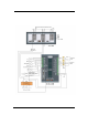
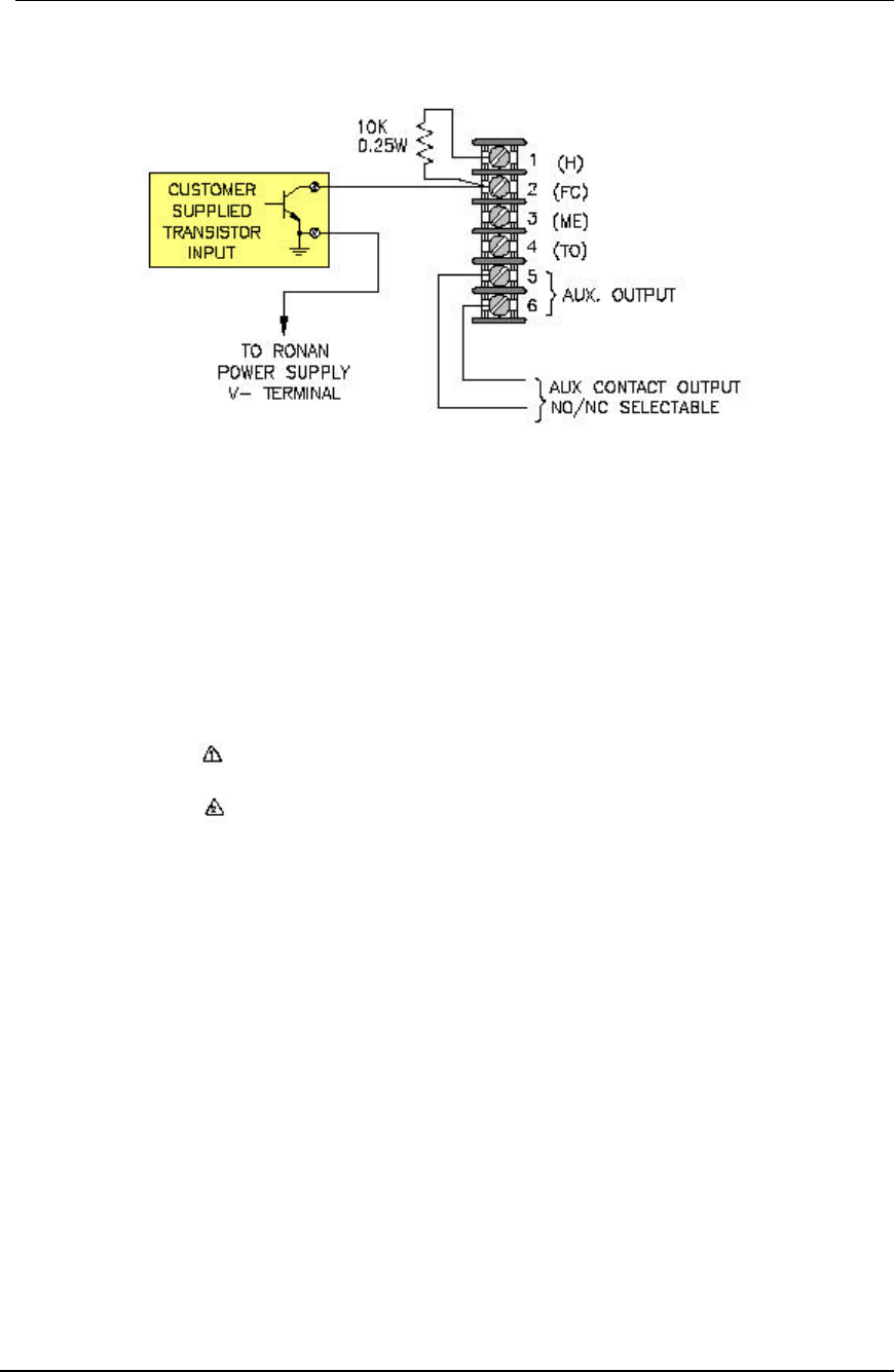
Figure 2-19 Typical transistor input (DWG NO: X11C497)
(H)
:
Field contact voltage for dry contact
(FC)
:
Field contact return
(ME)
:
Connect all First out windows in a
group.
(TO)
:
Transistor output driver.
AUX OUT
:
Auxiliary output - N.O./N.C. selectable
:
T.O.: A1, A2, CTA, RFL, RUN for
transistor driver
:
A1, A2, CTA, RFL, RUN for auxiliary
output
NO
:
Normally opened
COM
:
Common
NC
:
Normally closed.
A1
:
Horn 1
A2
:
Horn 2.
CTA
:
Common Trouble Alarm
RFL
:
Reflash
RUN
:
X11CA-IM power indication
GP1, GP2
:
Programmable inhibit function.