Series X16PDM Computer Annunciators Hardware Manual REVISION: DOCUMENT NUMBER: DATE: EDITOR: 1.0 X16PDM-3002 1/6/03 Nana Lee, Mark Layos Ronan Engineering Company APPROVED: __V.J.____________________________________ __1-14-03_______ __R.H.____________________________________ __1-14-03_______ __A.G.
Rev 1.0 Series X11CA Common Alarm Annunciator Systems Operating Manual: Revision Log REVISION LOG Rev # Description 1.
Rev 1.0 Series X11CA Hardware Manual: Table of Contents 1. OVERVIEW.......................................................................................................................... 1 1.1 Abbreviations..................................................................................................................................................................... 2 1.2 Revision History ................................................................................................................
Rev 1.0 Series X11CA Hardware Manual: Table of Contents 2.8 Troubleshooting............................................................................................................................................................... 25 2.8.1 General .....................................................................................................................................................................25 2.8.2. Non-operating Alarm System..........................................................
Rev 1.0 Series X11CA Hardware Manual 1. Overview 1. Overview The RONAN Series X11CA Computer Annunciator system is a state of art annunciator group system, designed to provide the most advanced data acquisition and monitoring system that meet the requirement of the process and power industries in the most economic way. The X11CA-Interface Module of the system provides advanced communication protocols to interface the external host computer, local network or plant network.
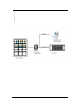
Rev 1.0 Series X11CA Hardware Manual 1. Overview § § § § § § The maximum of 256 modules are allowed per system. Microprocessor Based system High noise immunity Field proven off-the shelf worldwide Serial input/output Comprehensive user configuration with standard windows software Figure 1-1 X11CA System 1.
Rev 1.0 Series X11CA Hardware Manual 1. Overview 1.2 Revision History Revision 0.1 Revision 0.2 Revision 1.0 : : : First Draft Second Draft First approved and released document 1.3 References QA400 : Design Control : Design Development Quality Assurance Plan : Project Archive QA4000 QA4500 X11CA-3000 X11CA-3001-IOM : X11CA-IM Master Modules : X11CA Configuration Software User’s Manual 1.4 Specifications and Power Requirements 1.4.
Rev 1.0 Series X11CA Hardware Manual 1. Overview 1.4.3 Temperature Range § § Operating – 0° to 60° C (32° to 140° F) Storage - -40° to +85° C (-40° to + 185° F) 1.4.4 Inputs § § § Contact – Dry or Live; Normally Open / Normally Closed Field Selectable Interrogation Voltage – 24 Vdc, 48 Vdc, 125 Vdc, 115 Vac, or 240 Vac 1.4.5 Response Time § 20 Milliseconds by default. It can be modified using the X11CA Configuration software. 1.4.6 EMI/RFI Compatibility § CE Compliant 1.4.
Rev 1.0 Series X11CA Hardware Manual 1. Overview 1.4.10 Communications § § Serial – RS485 (P1) to External Host Network – RJ45 (TCP/IP) to External Host 1.4.11 Serial Protocols § MODBUS RTU, Allen Bradley, DF1, DNP 3.0, Ronan Proprietary 1.4.12 Network Protocols § TCPIP (OPC) 1.4.13 Serial § § RS232 (P2) – System Sequence and Option Programming via Laptop or Computer Software – Ronan X11CA Configuration 1.4.
Rev 1.0 Series X11CA Hardware Manual 2. X11CA Hardware Setup 2. X11CA Hardware The RONAN X11CA Computer Annunciator System with microprocessor based electronics is assembled from basic 3.50 inch (88.90 mm) by 3.50 inch (88.90 mm) modules to make up the overall size requirements and number of windows required.
Rev 1.0 Series X11CA Hardware Manual 2.
Rev 1.0 Series X11CA Hardware Manual 2.
Rev 1.0 Series X11CA Hardware Manual 2.
Rev 1.0 Series X11CA Hardware Manual 2. X11CA Hardware Setup 2.1.6 Quadalarm Module: Part NO: X11CA-4000 The four windows Quadalarm Module represent the highest density of annunciation in the X11CA series. The 1.40 inch (35.56 mm) high by 1.40 inch wide window is illuminated by two 1-watt lamps or LED indicators.
Rev 1.0 Series X11CA Hardware Manual 2. X11CA Hardware Setup 2.2 X11CA Alarm Module: Part NO. X11-1047 Figure 2-7 X11-1047C Module 2.2.1 Power Sources The external 24 VDC power is supplied to the V+ jumper connector J5 (pin 7,15) and to the V- jumper connector J5 (pin 8,16) on the PC board. The voltage regulator, VR2, and two resistors, R59 and R63, on the board reduce the voltage down to 5 VDC.
Rev 1.0 Series X11CA Hardware Manual 2. X11CA Hardware Setup 2.2.2 Field Contact Inputs Field contacts can be set as normally open or normally closed by setting jumper switches (J11, J6, J7, and J8) either as NO or NC on each alarm module. • • • Dry contact – The system internal interrogation powered 24 Vdc. Live contact – 0pto-isolated inputs. The opto-couplers, U1, U5, U7 and U11, provide 2,500-volt isolation. 24 Vdc, 48 Vdc, 125 Vdc or 115 Vac, 240 Vac 2.2.
Rev 1.0 Series X11CA Hardware Manual 2. X11CA Hardware Setup 2.2.5 RS485 Network The X11CA Annunciator uses a typical RS-485 four-wire multidrop configuration system. All slave modules communicate with the master module, X11CA IM only, and the address of each slave module is selectable by the jumper, J9, using the binary code. Jumper 9 Each X11CA module board must have a unique binary address to communicate with the X11CA Configuration program and the X11CAIM.
Rev 1.0 Series X11CA Hardware Manual 2. X11CA Hardware Setup J9 Address of the alarm module. Each alarm module must have a unique address number. For the address setting, refer to the Appendix B: Data Conversion (Bin to Dec) Table on page 40. J10 Used for activating the boot trap loader during the first programming time into the firmware Polarity of field input contact A. Either Normally Open or Normally Closed. Converter from R485 to TTL for Receiver and Transmission.
Rev 1.0 Series X11CA Hardware Manual 2. X11CA Hardware Setup Figure 2-9 Jumper Setting on the Quad Relay Circuit 2.4 Cables 2.4.1 X11CA to X11CA-IM without PB Figure 2-10 Cable for X11CA to X11CA-IM Connection 2.4.
Rev 1.0 Series X11CA Hardware Manual 2. X11CA Hardware Setup Figure 2-11 RS232 Cable from Host PC to X11CA-IM Connection 2.5 Mounting Refer the mounting diagrams on the enclosed CD ROM, X11CA Drawings and Sequence Chart, for detail. 2.5.1 Mounting the Modules in the Alarm Cabinet The annunciator is shipped with all of the alarm/lamp modules, auxiliary contact module(s) and flasher module(s) installed in the cabinet, as specified by purchase order.
Rev 1.0 Series X11CA Hardware Manual 2.
Rev 1.0 Series X11CA Hardware Manual 2.
Rev 1.0 Series X11CA Hardware Manual 2. X11CA Hardware Setup 2.6 Wiring Instructions The following diagrams show rear terminal arrangement and wiring for the X11CA2000 system and the X11CA-4000 system. For other wiring diagrams, refer to the wiring diagrams on the CD. 2.6.
Rev 1.0 Series X11CA Hardware Manual 2. X11CA Hardware Setup 2.6.
Rev 1.0 Series X11CA Hardware Manual 2. X11CA Hardware Setup Figure 2-19 Typical transistor input (DWG NO: X11C497) (H) : Field contact voltage for dry contact (FC) : Field contact return (ME) : Connect all First out windows in a group. (TO) : Transistor output driver. AUX OUT : Auxiliary output - N.O./N.C. selectable NO COM NC A1 A2 CTA RFL RUN GP1, GP2 : T.O.: A1, A2, CTA, RFL, RUN for transistor driver : A1, A2, CTA, RFL, RUN for auxiliary output : Normally opened : Common : Normally closed.
Rev 1.0 Series X11CA Hardware Manual 2. X11CA Hardware Setup Alarm Terminal Inputs Two basic types of terminal contacts are available. i. Dry contact. Figure 2-20. With 24Vdc system power Figure 2-21. With 48Vdc, 5Vdc, 10Vdc, 125Vdc FC Source FC source must be common to the system FC. ii. Opto-Coupled (Live contact) Figure 2-22. With FC source 24 Vdc/Vac, 48Vdc/Vac, 120/Vac Each active alarm input must be wired to a customer’s sensing device to set its alarm condition as either open or closed.
Rev 1.0 Series X11CA Hardware Manual 2. X11CA Hardware Setup The return wire from the field contact is wired to the FC terminal on each respective alarm module. Since the alarm system provides the power to the field contacts, it is important to verify that no other voltage source is present on either the H or FC terminals. NOTE: Please refer to the transmitter drawing on the enclosed CD. In general, the solid-state alarm system is a floating system.
Rev 1.0 Series X11CA Hardware Manual 2. X11CA Hardware Setup 2.. AC to DC Converter 115 115 115 116 115 220 220 220 220 220 115 115 115 115 115 115 115 115 115 - 24 24 24 24 24 24 24 24 24 24 24/125 24/125 24/125 24/125 24/125 24 24 24 24 - 125 250 375 500 750 125 250 375 500 750 125 250 375 500 750 250DA 375DA 500DA 750DA Diode Grated Output Power Output Watts DC Voltage Out AC Voltage In In case of multiple supply of input, make the parallel V+ and Vconnections. 2.7.
Rev 1.0 Series X11CA Hardware Manual 2. X11CA Hardware Setup Upon the power application, the flasher module within the system will automatically initiate reset cycle. If all the associated field contacts are in normal condition, the system should then be in a quiescent state with the horn(s) off and no lamps flashing. Press the TEST button. (Refer to the sequence charts on the CD for the expected results.) 2.8 Troubleshooting 2.8.
Rev 1.0 Series X11CA Hardware Manual 2. X11CA Hardware Setup 2.9.1 .
Rev 1.0 Series X11CA Hardware Manual 2. X11CA Hardware Setup Figure 2-24 Dimensional Information of X11CA RR-4000 (DWG NO.
Rev 1.0 Series X11CA Hardware Manual 3. Event Sequences 3. Event Sequences Typical alarm sequence specification for the X11CA is as follows. Figure 3-1 Typical Alarm Sequence Specifications. 3.1 Options The following list has the types of options used for the X11CA.
Rev 1.0 Series X11CA Hardware Manual 3. Event Sequences Options 1. Descriptions Silence Pushbutton: A separate pushbutton is added to allow silencing the alarm audible device without affecting the visual displays. Figure 3-2 Silence Pushbutton Option 4 No Lock-in: Figure 3-3 No Lock-in Option 5 No Flashing: 6 No Alarm Audible No outputs on Terminals A1 and A2. 3.2 Basic Sequence Types The descriptions of the basic sequence types are listed below.
Rev 1.0 Series X11CA Hardware Manual 3. Event Sequences A M Automatic Reset: The sequence returns to the normal state automatically, after the event returns to normal and acknowledged. Manual Reset: The sequence returns to the normal state, after the event returns normal, acknowledged, and reset. 3.3 First-out Sequence First out sequences indicate which one of a group of alarm points operated first.
Rev 1.0 Series X11CA Hardware Manual 3. Event Sequences 3.4 Sequences of X11CA 3.4.1 A-1 Automatic Reset The audible device is silenced and flashing stops when acknowledged. Acknowledgement of the alarm resets automatically when the event returns to normal.
Rev 1.0 Series X11CA Hardware Manual 3. Event Sequences 3.4.2 F1A-1 First Out with Automatic Reset The First Alarm operates as a basic sequence A. Subsequent alarms operate as a status lamp. The visual display of the subsequent alarms is steady on until the events return to normal, at which time the lamplights go off. Key applications: 1. 2. 3. 4. If First out is the only alarm of importance. Current status of the subsequences is of interest.
Rev 1.0 Series X11CA Hardware Manual 3. Event Sequences 3.4.3 F1M-1 First out with manual reset The first alarm operates as a basic sequence M. Subsequent alarms operate as a status lamp that locks in until the events return to normal and Reset is initiated.
Rev 1.0 Series X11CA Hardware Manual 3. Event Sequences 3.4.4 F2A -1 First out automatic reset. The first alarm operates as a basic Sequence A. subsequent alarms operate as a status lamp and also activates the audible devices. Option 1 must be used to enable the apparent operation of the audible for subsequent alarms. Subsequent alarms are locked-in and cannot return to the normal state until the Acknowledge pushbutton is activated, resetting the first out-alarm.
Rev 1.0 Series X11CA Hardware Manual 3. Event Sequences 3.4.5 F2M-1 First Out Manual Reset The First out alarm operates as a basic sequence M. Subsequent alarms operate as a status lamp and also operate the audible. Before acknowledging the First out alarm, sequence F2M operates the same as sequence F2A. After acknowledgement, sequence F2M differs by requiring a Reset to return to normal even though the events have returned to normal.
Rev 1.0 Series X11CA Hardware Manual 3. Event Sequences 3.4.6 F3A-1 First out. Displaying the visual device in intermittent flashing pattern and activating the audible devices until the first function is reset distinguish the first alarm. The acknowledged first alarm is distinguished by changing the visual display as slow flashing. Subsequent alarms follow the basic sequence A.
Rev 1.0 Series X11CA Hardware Manual 3. Event Sequences 3.4.7 F3M-1 First out manual reset. The first out alarm in a group is distinguished by unique display until the first out function is reset. Because Acknowledge is not used to reset the first out function, the new first alarm and subsequent alarms can be acknowledged so that the new alarms can be distinguished from the previously acknowledged alarms.
Rev 1.0 Series X11CA Hardware Manual 3. Event Sequences 3.4.8 M-1 Manual Reset Sequence M is a basic alarm sequence (Horn on with Flashing Visual) with Manual Reset that retains acknowledged alarms until the process input conditions return to normal and the manual Reset pushbutton is activated. In some applications, Sequence M may have a disadvantage since new alarms that occur while the Acknowledge Pushbutton is being operated appear in the steady on condition.
Rev 1.0 Series X11CA Hardware Manual 4. Appendix A: List of Figures 4. Appendix A: List of Figures FIGURE 1-1 X11CA S YSTEM ............................................................................................... 2 FIGURE 2-6 QUADALARM PLUG IN MODULE ....................................................................... 11 FIGURE 2-7 X11-1047C MODULE ..................................................................................... 11 FIGURE 2-8 SUMMARY OF THE X11-1047 JUMPER SETTINGS .........
Rev 1.0 Series X11CA Hardware Manual 5. Appendix B: Data Conversion (Bin to Dec) Table 5. Appendix B: Data Conversion (Bin to Dec) Table The following list shows numbers from 0000 00012 (110 ) to 1111 11112 (25510).
Rev 1.0 Series X11CA Hardware Manual 5.
Rev 1.0 Series X11CA Hardware Manual 5.
Rev 1.0 Series X11CA Hardware Manual 5.
Rev 1.0 Series X11CA Hardware Manual 5.
Rev 1.0 Series X11CA Hardware Manual 5.
Rev 1.0 Series X11CA Hardware Manual 5.
Rev 1.0 Series X11CA Hardware Manual 6. INDEX 6. INDEX Mounting · 16 Specifications · 28 Specifications Communications · 5 System Specifications Approvals · 5 Communications · 5 Controls · 4 Diagnostic · 4 EMI/RFI Compatibility · 4 Inputs · 4 Outputs · 4 Power source · 3 Response time · 4 Serial · 5 Special Feature · 5 System Size · 5 system voltage · 3 System Weight · 5 Temperature Range · 4 Warranty · 5 System Specifications · 3 P W Part NO. X11-1047 · 11 Part NO.
Rev 1.0 Series X11CA Hardware Manual 6.
Rev 1.0 Series X11CA Hardware Manual 6.