Series X11CA/X16PDM Computer Annunciators/ Programmable Digital Monitors Configuration Software User’s Manual REVISION: DOCUMENT NUMBER: DATE: EDITOR: 1.3 X11CA-3001-IOM 3/13/2003 Nana Lee, Mark Layos Ronan Engineering Company APPROVED: _Vassil__Jotev___________________________ _3/13/03_ Project Manager Date __Razmik Haftvai ________________________ __3/13/03_ Engineering Manager Date ___Tony Gasca___________________________ __3/13/03_ Q.A.
Rev 1.3 Series X11CA Computer Annunciators: X11CA Configuration Software User’s Manual Revision Log REVISION LOG Rev # 1.0 1.1 1.2 1.3 Description Changed the title from’Common Alarm Annunciator System’ to ‘Computer Annunciators’. Software was upgraded from v2.0 to v2.0.50: ECO# 11774 Title was changed:Added X16PDM: Sec 4.5.
Rev 1.3 Series X11CA Computer Annunciators: X11CA Configuration Software User’s Manual Table of Contents 1. OVERVIEW.............................................................................................................. 1 1.1 1.2 1.3 Abbreviations .........................................................................................................2 Revision History.....................................................................................................3 References .................
Rev 1.3 Series X11CA Computer Annunciators: X11CA Configuration Software User’s Manual Table of Contents 7. INDEX......................................................................................................................
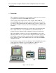
Rev 1.3 Series X11CA Computer Annunciators: X11CA Configuration Software User’s Manual 1. Overview 1. Overview The Configuration Software runs on a host computer to make it easy for an operator to program and test the X11CA/X16PDM alarm modules. A basic system consists of three devices: a host computer, X11CA-IM, and X11CA/X16PDM chassis.
Rev 1.3 Series X11CA Computer Annunciators: X11CA Configuration Software User’s Manual 1. Overview Figure 1-2 X16PDM System 1.
Rev 1.3 Series X11CA Computer Annunciators: X11CA Configuration Software User’s Manual 1. Overview 1.2 Revision History Revision 1.0 Revision 1.1 1.3 Revision 1.2 : First approved and released document : Updated due to software update from V2.0 to V2.0.50: ECO# 11774 : Title includes X16PDM:Added X16PDM: Sec 4.5. Revision 1.
Rev 1.2 Series X11CA Computer Annunciators: X11CA Configuration Software User’s Manual 3. X11CA Installation and Un-installation 2. Requirements The following is a list of system requirements for installing and running the Configuration Software. ? ? ? Windows 95/98/NT/XP Operating System The most recent firmware of unit 16 on the X11CA-IM: checksum The most recent firmware of unit 2 on each module (part number: X11-1047PL1 R1): X11CAV1.0 19200.
Rev 1.3 Series X11CA Computer Annunciators: X11CA Configuration Software User’s Manual 3. X11CA Installation and Un-installation 3. Software Installation and Un-installation 3.1 Installing the Configuration Software Software 1) 2) 3) 4) 5) 6) Turn on the power to the computer. Close all the other running programs. Insert the Installation CD into the CD driver. Double-click on the My Computer icon on the desktop. Double-click on the CD ROM drive that has the installation disk.
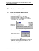
Rev 1.3 Series X11CA Computer Annunciators: X11CA Configuration Software User’s Manual 3. X11CA Installation and Un-installation If you want to change the directory, click on the Change Directory button to select a destination directory as shown in Figure 3-3 When you are ready to continue the installation, click on the installation icon button in the middle of the window to continue the installation.
Rev 1.3 Series X11CA Computer Annunciators: X11CA Configuration Software User’s Manual 3. X11CA Installation and Un-installation 10) The installation program will install the software. When the X11CA Setup is completed successfully, click on the OK button. 3.2 Uninstalling the Configuration Software Software 1) 2) 3) 4) 5) 6) 7) Left-click on the Start button on the desktop. Select the Settings. Select the Control Panel. Double click on the Add/Remove Programs icon.
Rev 1.3 Series X11CA Computer Annunciators: X11CA Configuration Software User’s Manual 4. X11CA Software Operation 4. Configuration Software Operation The main function of the Configuration Software is easy configuration and testing of the alarm modules in the X11CA/X16PDM chassis. This function involves two types of modules: physical module and logical module. A physical module is an alarm module in the X11CA/X16PDM chassis.
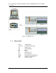
Rev 1.3 Series X11CA Computer Annunciators: X11CA Configuration Software User’s Manual 4. X11CA Software Operation Exampl e: Fi gure 4-1 (Modul e1:3 channel s, Modul e2:4 channel s) Figure 4-1 shows a X11CA system with two physical modules. Each physical module has a unique address. The first module has three channels and the second module has four channels. Figure 4-1 System Setup This example will continue throughout this document.
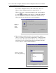
Rev 1.3 Series X11CA Computer Annunciators: X11CA Configuration Software User’s Manual 4. X11CA Software Operation 4.1 Loading the Configuration Program 1. Click on the Start button. 2. Select Programs. 3. Click on the program name you have selected during the installation process. The following example shows the program name as X11CA. Figure 4-2. Starting Configuration Software 4.2 The Main Window After the software is loaded, the Main window opens.
Rev 1.3 Series X11CA Computer Annunciators: X11CA Configuration Software User’s Manual 4. X11CA Software Operation Figure 4-3 Main Window 4.2.1 The Title Bar The first line at the top of the Main window is the Title area. It displays two names: the Configuration Software name and the configuration file name. Example: The title bar on Figure 4-3 shows that the name of the program is ‘X11CA’ and the configuration file name is ‘untitled’. 4.2.
Rev 1.3 Series X11CA Computer Annunciators: X11CA Configuration Software User’s Manual 4. X11CA Software Operation .File (ALT+F) Module (ALT+M) System (ALT+S) Setup (ALT+E) Help (ALT+H) New Open (Ctrl+O) Save (Ctrl+S) Save As Access Info Exit Config Config Commport Password About Run Stop Receive Program Connect Disconnect Run Stop Receive Program SaveReportAs PrintReport Figure 4-4.
Rev 1.3 Series X11CA Computer Annunciators: X11CA Configuration Software User’s Manual 4. X11CA Software Operation Submenus Config Run Description Opens Module Properties window. (See Figure 4-14. Module Properties Window.) The highlighted logical module cell on the Main window that has communication with its physic al module becomes green and displays ‘Run’ message. (See Figure 4-33. Modules in Run Mode.) If connection to the physical modules is active, the physical module is ready to be tested.
Rev 1.3 Series X11CA Computer Annunciators: X11CA Configuration Software User’s Manual 4. X11CA Software Operation Submenu Config Connect Disconnect Run Description Opens Module Properties window. (See Figure 4-14. Module Properties Window.) This function is same as the Config submenu of Module menu. Makes connection between the logical modules and the physical modules. Disconnects from the physical modules.
Rev 1.3 Series X11CA Computer Annunciators: X11CA Configuration Software User’s Manual 4. X11CA Software Operation SETUP (ALT+E) menu Submenu CommPort Password Description Opens Setup window where you can set up the communication port and its baud rate. (See Figure 4-9 Communication Port Window.) Opens Set Password window where you can change the password for programming the micro-controllers. (See Figure 4-40. Set Password Window.
Rev 1.3 Series X11CA Computer Annunciators: X11CA Configuration Software User’s Manual 4. X11CA Software Operation If you place the cursor underneath each icon, its name will display under the icon. Name New Description Opens a new configuration file. Pressing this button also resets the Configuration Software. Opens a window that has a list of existing files to be selected from. Open Save Properties Connect Saves the current properties into the currently open configuration file.
Rev 1.3 Series X11CA Computer Annunciators: X11CA Configuration Software User’s Manual 4. X11CA Software Operation Figure 4-7 System Display Field 1) Module Display Table Area Each cell on the table represents a logical module with a unique address that is same as its physical address. A status message of the logical module, such as No Comm., Run, Stop, Erased or Programmed, can be displayed in the cell. The following table has descriptions of each message.
Rev 1.3 Series X11CA Computer Annunciators: X11CA Configuration Software User’s Manual 4. X11CA Software Operation If it is double clicked, it opens its Module Properties window where you can view or modify properties of the logical module 2) Module Status Area This area displays following information for a selected module. Number Status Descriptions The address of the logical module.
Rev 1.3 Series X11CA Computer Annunciators: X11CA Configuration Software User’s Manual 4. X11CA Software Operation Figure 4-8. Push Button Field PB T Buttons Test S A R F.R. Silence GF1 GF2 4.2.5 Acknowledge Reset First Out Reset General Function 1 General Function 2 Status Bar Status Settings This area displays the communication port settings, such as baud rate, parity, data bits, and stop bit. Table 4-8. Status Bar 4.
Rev 1.3 Series X11CA Computer Annunciators: X11CA Configuration Software User’s Manual 4. X11CA Software Operation Figure 4-9 Communication Port Window 2) The following table shows available options and default values of each category on the Comport window. Select the settings appropriately. Port Max Speed Default Values Com1 19200 Other values Com2, Com3, … Com 16 8800, 38400, 56000, 57600, 115200, 128000, 256000 NOTE: Currently two baud rates are available for X11CA-IM operation: 19200 and 38400.
Rev 1.3 Series X11CA Computer Annunciators: X11CA Configuration Software User’s Manual 4. X11CA Software Operation 3) To retrieve physical module properties to the logical modules, Section 4.4.1.Setting System Properties, Section 4.6 Connecting to Physical Alarm Modules, and then Section 4.4.7 Retrieving Properties from a Configuration File. Before you start configuring the system and module properties, it is better to get all the information. § § § § § § § § § § § § § 4.4.
Rev 1.3 Series X11CA Computer Annunciators: X11CA Configuration Software User’s Manual 4. X11CA Software Operation If there are multiple physical modules in the chassis, the table has to be expanded. If you are not sure how many modules you have, check the purchase order. Follow the instructions below to set up the Module Display area. 1) Click on the System menu, and then Config to open the Setup System window. (Or press and then key).
Rev 1.3 Series X11CA Computer Annunciators: X11CA Configuration Software User’s Manual 4. X11CA Software Operation Example: If you have three alarm modules, you can set the width to 1 and the high to 3, or the width to 3 and the high to 1. Test Types This function is for testing the properties of physical alarm modules. For testing see Section 4.11Testing Alarm Modules . There are two types of testing depending on the switch setting on the X11CAIM.
Rev 1.3 Series X11CA Computer Annunciators: X11CA Configuration Software User’s Manual 4. X11CA Software Operation Horn Types Continuous AutoSilence 5 sec AutoSilence 30 sec AutoSilence 1 min AutoSilence 30 min Description Horn sounds continuously until it is silenced Horn sounds for 5 seconds and then drops out automatically. Horn sounds for 30 seconds and then drops out automatically. Horn sounds for 1 minute and then drops out automatically. Horn sounds for 30 minute and then drops out automatically.
Rev 1.3 Series X11CA Computer Annunciators: X11CA Configuration Software User’s Manual 4. X11CA Software Operation § § CTA (NO) turns ON. When the acknowledge button connected to the X11CA-IM is pressed, CTA turns OFF. When the Field Contact returns to normal, there is no CTA signal. If the Field Contact input is normally energized § § § ALARM (Alarm Simulator) When the Field Contact goes into alarm condition, CTA turns OFF.
Rev 1.3 Series X11CA Computer Annunciators: X11CA Configuration Software User’s Manual 4. X11CA Software Operation Serial Data Output Type: Data output follow Serial Data Output is the signal that is transmitted from TXD (transmittal data line) of the Port 2 on the X11CA-IM when X11CA-IM is in RUN mode. Example: The following table is based on the A-1 sequence type running in the X11CA-IM environment. The sequence chart is available on the CD provided.
Rev 1.3 Series X11CA Computer Annunciators: X11CA Configuration Software User’s Manual 4. X11CA Software Operation until the alarm is acknowledged. After that, the alarms return to normal and then reset. Table 4-13 Signals the Serial Data Output Follows After setting System properties, click on the OK button.
Rev 1.3 Series X11CA Computer Annunciators: X11CA Configuration Software User’s Manual 4. X11CA Software Operation NOTE: To adjust a cell size, position the cursor over the dividing line until the bidirectional arrow symbol (? ) appears and then drag the cursor in the direction you want to stretch or shrink. 4.4.2 Setting Module Properties Setting new module properties can be done on the Module Properties window. There are two ways to open it. 1) 2) Click on the Module menu, and then Config.
Rev 1.3 Series X11CA Computer Annunciators: X11CA Configuration Software User’s Manual 4. X11CA Software Operation 1) Changing the channel properties of the modules can be done in two ways. § § Select a module number from the Module Number box to set the address of the module. Select the number of channels for each module. Exampl e: Fi gure 4-1 (Modul e1:3 channel s, Modul e2:4 channel s) X11CA -IM Switch : PRGM Assume that the first module has 3 channels.
Rev 1.3 Series X11CA Computer Annunciators: X11CA Configuration Software User’s Manual 4. X11CA Software Operation 2) Left-click in the Channel 1 area of the Channel Properties box to open the Channel: 1 window. Figure 4-16. Channel Properties Window with Default Values ? Sequence Type There are twelve sequence types to choose from. They are F1M-1, F1A-1, F2M-1, F2A-1, F3A-1 F3M-1, A-1, A4, A-4-5-6, and M-1. Please refer to the Sequence charts on the CD.
Rev 1.3 Series X11CA Computer Annunciators: X11CA Configuration Software User’s Manual 4. X11CA Software Operation ? Auxiliary Relay Output Follow Choose the signal that will trigger the Auxiliary Relay Output signal from the X11CA-IM when the switch on the X11CA-IM is on Run side. The result depends on the sequence type of each channel. Figure 4-19 Auxiliary Relay Output Example: The following is the sequence of A-1 type inX11CA-IM environment.
Rev 1.3 Series X11CA Computer Annunciators: X11CA Configuration Software User’s Manual 4. X11CA Software Operation the X11CA-IM is pressed, auxiliary output becomes de-energized. If the Field Contact input is normally energized § § ALARM (Alarm Simulator) When the Field Contact goes into alarm condition, auxiliary output becomes deenergized. When the alarm is acknowledged on the X11CA-IM, the auxiliary output becomes energized.
Rev 1.3 Series X11CA Computer Annunciators: X11CA Configuration Software User’s Manual 4. X11CA Software Operation Normally Energized option for the relay output When FC, ACK, ALARM or HORN is chosen for the relaytriggering signal, the Normally Energized check box becomes activated. By default, the relay output is set to Normally NotEnergized. When this box is checked, the state of an event gets reversed, so that it stays active in its normal state, but inactive in its alarm state.
Rev 1.3 Series X11CA Computer Annunciators: X11CA Configuration Software User’s Manual 4. X11CA Software Operation § § When the Field Contact is in an alarm condition, transistor output turns OFF. When the Field Contact returns to normal condition, transistor output turns ON. If the input is normally not energized: § § ACK (Acknowledge) When the Field Contact goes into an alarm condition, transistor output turns ON. When the alarm is acknowledged, transistor output turns OFF.
Rev 1.3 Series X11CA Computer Annunciators: X11CA Configuration Software User’s Manual 4. X11CA Software Operation If the input is normally energized: § § When the Field Contact goes into alarm condition, the audio device becomes inactive. When the horn is silenced, the audio display turns ON. If the input is normally not energized: § § § LAMP ALARM When the Field Contact goes into alarm condition, the lamp starts fast flashing. When the alarm is acknowledged, the lamp becomes steady ON.
Rev 1.3 Series X11CA Computer Annunciators: X11CA Configuration Software User’s Manual 4. X11CA Software Operation ? HORN SELECTION Select the horns for the channel to run in the X11CA-IM environment. Figure 4-21 Horn Selection 3) Select the options. Click on the OK button to save the settings of the module and return to the Module Property window. Exampl e: Fi gure 4-1 (Modul e1:3 channel s, Modul e2:4 channel s) X11CA -IM Switch : PRGM Set the properties of channel one for the first module.
Rev 1.3 Series X11CA Computer Annunciators: X11CA Configuration Software User’s Manual 4. X11CA Software Operation Figure 4-23 New Channel1Properties 5) The next step is to configure the other channel(s). There are two ways to configure the other channel(s). ? ? If the other channels have different configurations, repeat the above steps for each channel. If the other channels have the same configuration as the first one, simply right click in the first channel area to copy from.
Rev 1.3 Series X11CA Computer Annunciators: X11CA Configuration Software User’s Manual 4. X11CA Software Operation 4.4.2.1 Setting the Common Signals Field This field consists of two areas: GF1 Inhibit area and GF2 Inhibit area. General Function (GF1) Inhibit When any of the following signals is checked, Configuration Software ignores its signal while the GF1 push button on the Main window is being pressed during the push button test time.
Rev 1.3 Series X11CA Computer Annunciators: X11CA Configuration Software User’s Manual 4. X11CA Software Operation Exampl e: Fi gure 4-1 (Modul e1:3 channel s, Modul e2:4 channel s) X11CA -IM Switch : PRGM Assume that the second module has four channels with F3M-1 as sequence type and all the other properties are same as the first module properties. Set the second logical module properties as shown in the figure below.
Rev 1.3 Series X11CA Computer Annunciators: X11CA Configuration Software User’s Manual 4. X11CA Software Operation 4.4.4 Saving System and Module Properties The current system properties and module properties can be saved into a file in two ways. 1) Click on the File menu and then save to save the currently open file. The default file name is untitled in the currently open directory. 2) To save the settings in a different file name, select the File menu and then SaveAs submenu.
Rev 1.3 Series X11CA Computer Annunciators: X11CA Configuration Software User’s Manual 4. X11CA Software Operation Exampl e: Fi gure 4-1 (Modul e1:3 channel s, Modul e2:4 channel s) X11CA -IM Switch : PRGM Open the File menu and then Access Info. The File Access Info window will open to display information about the sample-config.cfg file. Figure 4-29 File Access Info Window 4.4.6 Creating a New Configuration File In order to create a new configuration file, click on the File menu and then New submenu.
Rev 1.3 Series X11CA Computer Annunciators: X11CA Configuration Software User’s Manual 4. X11CA Software Operation Exampl e: Fi gure 4-1 (Modul e1:3 channel s, Modul e2:4 channel s) X11CA -IM Switch : PRGM Close all the open windows and then click on the File menu and then the Exit submenu to exit from Configuration Software. Run Configuration Software again. Click on the File menu and then the Open submenu to open the sampleconfig.cfg file.
Rev 1.3 Series X11CA Computer Annunciators: X11CA Configuration Software User’s Manual 4. X11CA Software Operation § § § § Configuration file name. Date and time created. Last date and time the file was accessed. Last date and time the file was modified. 2. Global system properties. 3. Alarm modules properties. 4. Error descriptions if an error occurred.
Rev 1.3 Series X11CA Computer Annunciators: X11CA Configuration Software User’s Manual 4. X11CA Software Operation Exampl e: Fi gure 4-1 (Modul e1:3 channel s, Modul e2:4 channel s) X11CA -IM Switch : PRGM Click on the System menu and then the PrintReport submenu. Verify that the information is correct and there is no error messages. X11CA SYSTEM REPORT. File Access Info: C:\ \SAMPLE-CONFIG.
Rev 1.3 Series X11CA Computer Annunciators: X11CA Configuration Software User’s Manual 4. X11CA Software Operation X11CA-IM in order to configure the physical alarm modules. The green RUN LED on the X11CA-IM device keeps blinking at the same time. Connection can be established in one of the following two ways. 1) Click on the Connect icon . 2) Click on the System menu, followed by Connect from the submenu.
Rev 1.3 Series X11CA Computer Annunciators: X11CA Configuration Software User’s Manual 4. X11CA Software Operation ? ? ? ? ? ? ? 4.7 A ‘Run’ message displays in the green cell of each active module cell. A ‘N.C’ message displays in the white cell of each inactive module. The Stop icon ( ) turns red. On each module status cell, the module number and its status display. On the status area, the com port settings display The Push Button field displays at the right side of the window.
Rev 1.3 Series X11CA Computer Annunciators: X11CA Configuration Software User’s Manual 4. X11CA Software Operation Exampl e: Fi gure 4-1 (Modul e1:3 channel s, Modul e2:4 channel s) X11CA -IM Switch : PRGM The following changes will be shown on the System Display screen after stopping the modules from running. Results: Figure 4-34 Modules in Stop Mode 4.8 ? ? ? A ‘Stop’ message appears in each red active module cell. A ‘No Comm.’ message appears in each white inactive module cell.
Rev 1.3 Series X11CA Computer Annunciators: X11CA Configuration Software User’s Manual 4. X11CA Software Operation The micro-controller on the target physical module picks the data package addressed to its address and checks the code. If it is a programming code, it will save the data into its firmware. The data saved in the firmware is permanent until it is cleared or re-programmed. To program physical modules, follow the instructions below.
Rev 1.3 Series X11CA Computer Annunciators: X11CA Configuration Software User’s Manual 4. X11CA Software Operation Figure 4-36 Erase Confirmation Window in Programming Mode 8) Wait until the micro-controller completes programming. When the programming is done successfully, each logical module cell will display the message, ‘Programmed’, in the yellow background as shown in the Figure 4-37, and then returns to Stop mode.
Rev 1.3 Series X11CA Computer Annunciators: X11CA Configuration Software User’s Manual 4. X11CA Software Operation Figure 4-37 Programming the First Module ? ? ? The messages, ‘Stop’, ‘Erased’, ‘Programmed,’ and then ‘Stop’, display in the yellow logical module cell. The messages ‘Erasing’, ‘Programming’, ’Verifying’ and then ‘Stop’, display in the Module Status area near the bottom of the window. An ‘NoComm’ message appears in each white inactive logical module cell. The Run icon turns green.
Rev 1.3 Series X11CA Computer Annunciators: X11CA Configuration Software User’s Manual 4. X11CA Software Operation send a packet that has its address and the copy of the data in its firmware to Configuration Software via X11CA-IM. Configuration Software will place the data into the corresponding logical module. In order to retrieve the properties from the modules, verify the followings. 1) 2) 3) 4) 5) The Configuration Software is in connection with the physical modules.
Rev 1.3 Series X11CA Computer Annunciators: X11CA Configuration Software User’s Manual 4. X11CA Software Operation If the switch on X11CA-IM is set to RUN, Configuration Software is ignored and X11CA-IM will take a full control of running its devices and the physical alarm modules. If the switch is on PRGM, X11CA-IM is bypassed and Configuration Software is ready to test physical alarm module properties. This section explains the later type.
Rev 1.3 Series X11CA Computer Annunciators: X11CA Configuration Software User’s Manual 4. X11CA Software Operation 4.11.1 Testing A Single Module 1) Before you start testing, makes sure that the logical module cell to be tested displays ‘Run’ message. 2) Click in a logical module cell on the Main window. 3) Click on the T button in the PB area. The test result depends on the test type set on the System Setup window.
Rev 1.3 Series X11CA Computer Annunciators: X11CA Configuration Software User’s Manual 4. X11CA Software Operation The operational test results depend on the sequence type of each channel. If any signal is set as inhibition signal for the Global Function keys, it can be tested. For the sequence process, refer to the sequence charts on the CD. Functions of the Push Buttons The following is the summary of the push button functions. PB T Buttons Test S Silence A Acknowledge R F.R.
Rev 1.3 Series X11CA Computer Annunciators: X11CA Configuration Software User’s Manual 4. X11CA Software Operation Exampl e: Fi gure 4-1 (Modul e1:3 channel s, Modul e2:4 channel s) X11CA -IM Switch : PRGM Click on the Run icon and then the T button. Results: Figure 4-39 Running the Test Push Button ? ? When the Test button is pressed, the active physical module lamps will light up according to the pre-set sequences.
Rev 1.3 Series X11CA Computer Annunciators: X11CA Configuration Software User’s Manual 4. X11CA Software Operation 4.12 Changing Password 1) To change the password, click on the Setup menu and then Password. 2) Enter the old password in the Old Password box. 3) Enter the new password in both the New Password box and the Verify box. Each letter of the password will appear as an asterisk (*) character for the security reason. 4) Click on the OK button. Figure 4-40.
Rev 1.3 Series X11CA Computer Annunciators: X11CA Configuration Software User’s Manual 5. Event Sequences 5. Appendix A: List of Tables Table 4-1 File Menu and Its Submenus............................................................................................ 12 Table 4-2 Module Menu and Its Submenus..................................................................................... 13 Table 4-3 System Submenu...........................................................................................
Rev 1.3 Series X11CA Computer Annunciators: X11CA Configuration Software User’s Manual 6. Appendix B: List of Figures 6. Appendix B: List of Figures Figure 1-1 X11CA System................................................................................................................................... 1 Figure 1-2 X16PDM System................................................................................................................................ 2 Figure 3-1 Extraction of the Installation File ..
Rev 1.3 Series X11CA Computer Annunciators: X11CA Configuration Software User’s Manual 6. Appendix B: List of Figures Figure 4-23 New Channel1Properties .............................................................................................................. 38 Figure 4-24 ............................................................................................................................................................ 38 Figure 4-25 Status of the First Module on the Main Window...............
Rev 1.3 Series X11CA Computer Annunciators: X11CA Configuration Software User’s Manual 7. INDEX 7.
Rev 1.3 Series X11CA Computer Annunciators: X11CA Configuration Software User’s Manual 7.