
Instruction Manual

Rev 2.0 : X11CA-IM MASTER MODULE
5
4 MODBUS COMMUNICATION PROTOCOL
4.1 Slave Address Setting
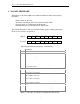
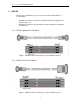
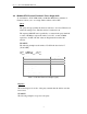
The Slave Address switch (SW1 or SW3, depending on the revision of the PCB) on
the X11CA-IM Module sets the Slave Address of the X11CA-IM Master Module
for MODBUS RTU communication as shown below.
Slave
address
SW1-1 SW1-2 SW1-3 SW1-4
1 OFF OFF OFF OFF
2 ON OFF OFF OFF
3 OFF ON OFF OFF
4 ON ON OFF OFF
5 OFF OFF ON OFF
6 ON OFF ON OFF
7 OFF ON ON OFF
8 ON ON ON OFF
9 OFF OFF OFF ON
10 ON OFF OFF ON
11 OFF ON OFF ON
12 ON ON OFF ON
13 OFF OFF ON ON
14 ON OFF ON ON
15 OFF ON ON ON
16 ON ON ON ON
Table 4-1 Setting Modbus Slave Address
4.2 Data Communication Format
The data format for Modbus communication is 19200, no parity, 8 bit and 1 stop
bit.
4.3 Modbus RTU Protocol Function 3: Read the Holding Registers
To read the binary contents of the holding registers on the X11CA-IM from a host
device, use Modbus RTU Protocol function 3.
Query
The query message specifies the starting register and the quantity of registers
to be read. Registers are addressed starting at zero: registers 1-16 are addressed
as 0-15.