
Instruction Manual

Rev 2.0 : X11CA-IM MASTER MODULE
3
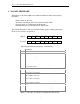
2 X11-MF3 FIRMWARE
The firmware on the X11CA-IM scans each X11CA alarm module for the following
information.
Field contacts (A, B, C, D),
H1 (Horn1), H2 (Horn2) and CTA (Common Trouble Alarm),
Operation mode for each channel (IA, IB, IC, ID),
First Out indication for each channel (FA, FB, FC, FD)
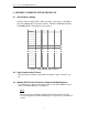
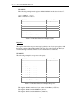
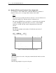
The scanned information is then stored into the holding registers, starting at the address
00, in two byte format as shown below.
Hi byte FD FC FB FA ID IC IB IA
Low byte S H2 H1 CTA
D C B A
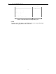
The following list has the descriptions of each data bit.
Descriptions
A Status of the first input
B Status of the second input
C Status of the third input
D Status of the forth input
CTA Status of Common Trouble Alarm
H1 Status of the Horn1
H2 Status of the Horn2
S Communication status bit: 0=Successful, 1=Failed to communicate with
X11CA Alarm modules.
IA Operation mode of Channel A. If IA=0, CH A is Contact Input.
If IA=1, CH A is serial input.
IB Operation mode of Channel B. If IB=0, CH B is Contact Input.
If IB=1, CH B is serial input.
IC Operation mode of Channel C. If IC=0, CH C is Contact Input.
If IC=1, CH C is serial input.
ID Operation mode of Channel D. If ID=0, CH D is Contact Input.
If ID=1, CH D is serial input.
FA If FA=1, CH A is the First Out channel within the group.
FB If FB=1, CH B is the First Out channel within the group.
FC If FC=1, CH C is the First Out channel within the group.
FD If FD=1, CH D is the First Out channel within the group.
Table 2-1 Descriptions of Modbus Communication Data Format