X11CA-IM MASTER MODULE (Firmware: X11-MF3 Rev. 3) REVISION DOCUMENT NUMBER DATE EDITOR APPROVED : : : : : APPROVED : APPROVED : 2.0 X11CA-3000-IOM April 21, 2003 Nana Lee Ronan Engineering Company Kevin Safayieh Project Manager Razmik Haftvani Engineering Manager Tony Gasca Q.A. Ronan Engineering 21200 Oxnard Street, Woodland Hills, CA 91367 TEL (818) 883-5211 FAX (818) 992-6435 Direct urgent problems to: 1-800-327-6626 Copyright 2003 Ronan Engineering Company. All rights reserved.
Rev 2.0 : X11CA-IM MASTER MODULE 1 OVERVIEW ..............................................................................................................1 1.1 Definitions ..............................................................................................................1 1.2 Revision History.....................................................................................................1 1.3 Reference Documents.................................................................................
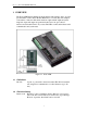
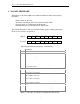
Rev 2.0 : X11CA-IM MASTER MODULE 1 OVERVIEW The X11CA-IM Interface Module monitors alarm module activities. It also provides special features, such as Slave Modbus RTU Protocol on Port (P2), time stamped event archive, common trouble alarm, dual horn output, reflash output and system diagnostic output. All outputs are generated in the form of an open collector transistor and selectable Form C dry contact. The LEDs on the board indicate serial communication and system status. Figure 1-1 X11CA-IM 1.
Rev 2.0 : X11CA-IM MASTER MODULE Revision 2.0 1.
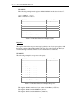
Rev 2.0 : X11CA-IM MASTER MODULE 2 X11-MF3 FIRMWARE The firmware on the X11CA-IM scans each X11CA alarm module for the following information. Field contacts (A, B, C, D), H1 (Horn1), H2 (Horn2) and CTA (Common Trouble Alarm), Operation mode for each channel (IA, IB, IC, ID), First Out indication for each channel (FA, FB, FC, FD) The scanned information is then stored into the holding registers, starting at the address 00, in two byte format as shown below.
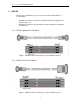
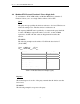
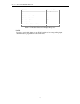
Rev 2.0 : X11CA-IM MASTER MODULE 3 CABLES The Port 2 is communication port to host device and can be either RS232 or isolated RS485. ? ? The RS485 connection is a 5 pin screw terminal and the pin assignments are marked on the cover. The RS232 connection is the 9 pin female connector and the pin assignments are listed below. 3.1.1 RS232: Laptop to X11CA-IM(P2) Figure 3-1 RS232 Cable from the Laptop to X11CA-IM Connection 3.1.
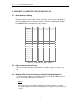
Rev 2.0 : X11CA-IM MASTER MODULE 4 MODBUS COMMUNICATION PROTOCOL 4.1 Slave Address Setting The Slave Address switch (SW1 or SW3, depending on the revision of the PCB) on the X11CA-IM Module sets the Slave Address of the X11CA-IM Master Module for MODBUS RTU communication as shown below.
Rev 2.0 : X11CA-IM MASTER MODULE EXAMPLE: The following example reads registers 40108-40110 from the slave device 17. 11HEX = 10001 BIN =17 DEC 6BHEX =1101011BIN =107 DEC Field Name Slave Address Function Starting Address Hi Starting Address L No. of Points Hi No.
Rev 2.0 : X11CA-IM MASTER MODULE 4.4 Modbus RTU Protocol Function 5: Force Single Cells To send alarms to X11CA-IM serially, use Modbus RTU Protocol function 5. Function 5 allows you to set a single window either to ON or OFF. Query The query message specifies the windows reference to be forced. Windows are addressed starting at zero. The first window is addressed as 0. The requested ON/OFF state is specified by a constant in the query data field. A value of FF 00 hex requests the window to be ON.
Rev 2.0 : X11CA-IM MASTER MODULE Field Name Slave Address Function Window Address Hi Window Address L Force Data Hi Force Data Lo Error Check (LRC or CRC) Example (Hex) 11 05 00 AC FF 00 -- Table 4-5 Modbus Function 5 Example-Response NOTE: In order to send serial alarms to any X11CA window, its corresponding input channel must be programmed to the serial mode.
Rev 2.0 : X11CA-IM MASTER MODULE 5 LED'S STATUS ? ? ? The RUN LED is a green color LED and starts flashing upon applying power to the unit. When flashing, it indicates the power in on and the firmware is running in the unit. The ERROR LED is RED and when flashes ON/OFF, it indicates one or more than one alarm boards not responding to the master module. The RXD1, TXD1, RXD2, TXD2 are amber color LEDs and they indicate the transmission and reception of data from port 1 and 2.
Rev 2.
Rev 2.
Rev 2.
Rev 2.
Rev 2.
Rev 2.0 : X11CA-IM MASTER MODULE 7 PRGM/RUN SWITCH Use the PRGM/RUN switch on the X11CA-IM to set the mode to either program mode or run mode. 7.1 Program Mode In the program mode, you can configure or change the configuration of the alarm modules with the Configuration software running on the host computer. To set X11CA-IM to program mode, set the switch to PRGM and make sure that the cable is connected from the Modbus communication port (P2) on the X11CAIM to the serial port of the host computer.
Rev 2.0 : X11CA-IM MASTER MODULE Button Name TEST Full Name Description Test Tests properties of alarm modules. SIL ACK RST FRST GF1 Silence Acknowledge Reset First Out Reset General Function 1 Stops the sound of the audio devices. Acknowledges the alarms. Resets inputs according to the sequence type. Resets the first out alarm in the group . GF2 General Function 2 Inhibits the GF2 inhibit signals while the button is being pressed.
Rev 2.0 : X11CA-IM MASTER MODULE 8 APPENDIX A: LIST OF TABLES TABLE 2-1 TABLE 4-1 TABLE 4-2 TABLE 4-3 TABLE 4-4 TABLE 4-5 TABLE 6-1 TABLE 7-1 DESCRIPTIONS OF MODBUS COMMUNICATION DATA FORMAT ..........................3 SETTING M ODBUS SLAVE ADDRESS ..................................................................5 MODBUS FUNCTION 3 EXAMPLE-QUERY...........................................................6 MODBUS FUNCTION 3 EXAMPLE-RESPONSE......................................................
Rev 2.0 : X11CA-IM MASTER MODULE 9 APPENDIX B: LIST OF FIGURES FIGURE 1-1 X11CA-IM.......................................................................................................1 FIGURE 3-1 RS232 CABLE FROM THE LAPTOP TO X11CA-IM CONNECTION .......................4 FIGURE 3-2 RS232 CABLE FROM THE LAPTOP TO X11CA-IM CONNECTION ......................