
Product Manual

Tool List:
Allen Wrench
(Supplied with your Roll-A-Ramp)
1/2” (13mm) Wrench
(Supplied with your Roll-A-Ramp)
Assembly:
Your Roll-A-Ramp has been
shipped assembled to your
specications. Ramps over 10 .
total length, please see addendum
enclosed with this manual for nal
assembly instructions.
General Information
Roll-A-Ramp is lightweight,
durable, and versatile. Fabricated
of strong anodized aerospace
aluminum, your Roll-A-Ramp will
provide years of carefree
convenience and accessibility
when used properly and for its
intended purpose.
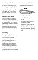
Using Your Roll-A-Ramp
To use your Roll-A-Ramp, lay the
rolled-up ramp on its side, remove
the strap, and then unroll the
ramp to its full length before
putting it in place. To roll up your
ramp, reverse the process, snap on
the strap, and go. It’s that simple!
You will notice that yellow pinch-
point covers are secured on the
head of each bolt. ese covers are
designed to keep your ngers out
of the “pinch zone” and must be
on at all times. Do NOT use your
ramp(s) without ALL Pinch Point
Covers in place. Never tamper
with or remove these covers for
any reason as injury may occur.
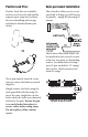
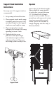
Ramp Placement: Important
To ensure safety and to prevent
damage to your ramp, you must
place the rst load-bearing link of
the elevated end of the ramp on the
landing. e approach plate is not
a load-bearing link. (See below)
Notice that one end of each ramp
is marked “Upper End.” is end
MUST ALWAYS be the elevated end
of the ramp. e links on the upper
end of your Roll-A-Ramp have a 1˚
camber and the links on the lower
end have a 0˚camber. is 0˚ lo
at the lower end of the ramp allows
the wheelchair, machine or other
device to get on the ramp on a non-
arched plane. As shown below, as the
wheelchair goes up the Roll-A-Ramp,