
Setup Guide


Machine Specications
41
Note
Be sure to use the expansion port within the rated range shown above.
Do not apply additional voltage to the terminal.
Do not short-circuit the terminal to ground.
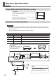
Expansion Port 2
PIN
number
Signal IN/OUT Overview/function
1 GND Connect this to the power supply GND.
2 Reserve RXD IN This is a spare output for communication.
3 Reserve RXD OUT This is a spare output for communication.
4 N.C.
5 Reserve Out1 OUT This is a spare general-purpose output.
6 Reserve Out2 OUT This is a spare general-purpose output.
7 Reserve Input1 IN This is a spare general-purpose output.
8 GND Connect this to the power supply GND.
9 ERROR OUT This signal activates when a fatal error occurs.
10 PAUSE OUT This signal activates when cutting is paused.
11 N.C.
12 Reserve 5V This is a spare 5 V power supply input for communi-
cation.
13 24V_EXT Connect this to the 24 V power supply. Prepare a power
supply that can supply 100 mA or more.
14 N.C.
15 N.C.
16 GND Connect this to the power supply GND.
17 N.C.
18 EMG_STOP IN Stop the machine.
19 SP_START OUT This signal activates during spindle rotation.
20 GND Connect this to the power supply GND.
21 GND Connect this to the power supply GND.
22 READY OUT This signal activates when cutting is possible.
23 BUSY OUT This signal activates when the machine is operating.
24 N.C.
25 24V_EXT Connect this to the 24 V power supply. Prepare a power
supply that can supply 100 mA or more.