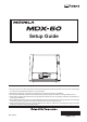
Setup Guide Thank you very much for purchasing this product. To ensure correct and safe usage with a full understanding of this product's performance, be sure to read through this document completely and store it in a safe location. Unauthorized copying or transferal, in whole or in part, of this document is prohibited. The contents of this document and the specifications of this product are subject to change without notice.
Applicable EMC Standards: EN 61326-1 (Class A), EN 55011 (Class A, Group 1), EN 61000-3-2, EN 61000-3-3 This product is a Class A device. Radio interference may occur if this product is used in a residential environment. In such cases, users of this product may need to implement appropriate measures. This product is a Group 1 device.
For the USA FEDERAL COMMUNICATIONS COMMISSION RADIO FREQUENCY INTERFERENCE STATEMENT This equipment has been tested and found to comply with the limits for a Class A digital device, pursuant to Part 15 of the FCC Rules. These limits are designed to provide reasonable protection against harmful interference when the equipment is operated in a commercial environment.
Operating Instructions KEEP GUARDS IN PLACE and in working order. REMOVE ADJUSTING KEYS AND WRENCHES. Form habit of checking to see that keys and adjusting wrenches are removed from tool before turning it on. KEEP WORK AREA CLEAN. Cluttered areas and benches invite accidents. DON'T USE IN DANGEROUS ENVIRONMENT. Don't use power tools in damp or wet locations, or expose them to rain. Keep work area well lighted. KEEP CHILDREN AWAY. All visitors should be kept safe distance from work area.
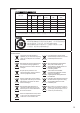
For China 产品中有毒有害物质或元素的名称及含量 有毒有害物质或元素 部件名称 铅(Pb) 汞(Hg) 镉(Cd) 六价铬 (Cr(Ⅵ)) 多溴联苯 (PBB) 多溴二苯醚 (PBDE) 印刷电路板 × ○ × ○ ○ ○ 头部 × ○ ○ ○ ○ ○ 壳体、底架 × ○ ○ ○ ○ ○ 电源 × ○ × ○ ○ ○ 其他(电缆、附件等) × ○ ○ ○ ○ ○ ○:表示该有毒有害物质在该部件所有均质材料中的含量均在 GB/T26572-2011 标准规定的限量要求以下。 ×:表示该有毒有害物质至少在该部件的某一均质材料中的含量超出 GB/T26572-2011 标准规定的限量要求。 环保使用期限 此标志适用于在中国国内销售的电子信息产品,表示环保使用期限的年数。 所谓环保使用期限是指在自制造日起的规定期限内,产品中所含的有害物质 不致引起环境污染,不会对人身、财产造成严重的不良影响。 环保使用期限仅在遵照产品使用说明书,正确使用产品的条件下才有效。 不当的使用,将会导致有害物质泄漏的危险。 For EU cou
Contents Contents.........................................................................................................4 To Ensure Safe Use..................................................................................5 Pour utiliser en toute sécurité................................................................. 11 Important Notes on Handling and Use.........................................................17 Installing the Machine.....................................................................
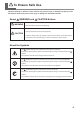
To Ensure Safe Use Improper handling or operation of this machine may result in injury or damage to property. Points that must be observed to prevent such injury or damage are described as follows. About WARNING and WARNING CAUTION Notices Used for instructions intended to alert the user to the risk of death or severe injury should the unit be used improperly. Used for instructions intended to alert the user to the risk of injury or material damage should the unit be used improperly.
To Ensure Safe Use Incorrect operation may cause injury WARNING Always unplug the power cord when attaching or removing parts and optional parts and when performing maintenance that does not require the machine to be connected to a power source. Attempting such operations while the machine is connected to a power source may result in injury or electrical shock. Keep children away from the machine.
To Ensure Safe Use Danger of electrical short, electrical shock, or fire WARNING Connect this machine to a power outlet that complies with this machine’s ratings (for voltage, frequency, and current). Incorrect voltage or insufficient current may cause fire or electrical shock. If sparks, smoke, burning odors, abnormal noise, or abnormal operations occur, immediately unplug the power cord. Never use the machine if any component is damaged.
To Ensure Safe Use WARNING Never use cutting oil. This machine is not designed for the flow of cutting oil. Oil may get inside the machine and cause fire or electrical shock. Never use a pneumatic blower. This machine is not compatible with a pneumatic blower. Cutting waste may get inside the machine and cause fire or electrical shock. Important Notes about the Power Cord, Plug, and Power Outlet Never place any object on top or subject to damage. Never bend or twist with excessive force.
To Ensure Safe Use Cutting waste and workpieces are flammable and toxic. WARNING CAUTION Never attempt to cut magnesium or any other such flammable material. Fire may occur during cutting. Never attempt to cut metal, carbon, or any other such conductive material. Fire may occur during cutting. Wear dust goggles and a mask. Wash away any cutting waste remaining on the hands. Accidentally swallowing or inhaling cutting waste may be hazardous to your health. Keep open flame away from the work area.
To Ensure Safe Use Warning labels Warning labels are affixed to make areas of danger immediately clear. The meanings of these labels are as follows. Be sure to heed their warnings. Also, never remove the labels or allow them to become obscured. Front Caution: Pinching Hazard Exercise caution to prevent fingers from being pinched when closing covers. Caution: Sharp Tool The cutting tool has a sharp point. Inadvertent contact may cause injury.
Pour utiliser en toute sécurité La manipulation ou l’utilisation inadéquate de cet appareil peuvent causer des blessures ou des dommages matériels. Les précautions à prendre pour prévenir les blessures ou les dommages sont décrites ci-dessous. Avis sur les avertissements Utilisé pour avertir l’utilisateur d’un risque de décès ou de blessure ATTENTION grave en cas de mauvaise utilisation de l’appareil.
Pour utiliser en toute sécurité Une utilisation incorrecte peut causer des blessures ATTENTION Toujours débrancher le câble d’alimentation lors de la fixation ou du retrait de pièces et de pièces en option et du nettoyage ou des travaux d’entretien qui n’exigent pas un branchement de l’appareil à une source d’alimentation. Tenter ces opérations pendant que l’appareil est branché à une source d’alimentation peut causer des blessures ou un choc électrique. Garder les enfants loin de l’appareil.
Pour utiliser en toute sécurité Risque de court-circuit, d’électrocution ou d’incendie ATTENTION ATTENTION Brancher à une prise électrique conforme aux caractéristiques de cet appareil (tension, fréquence et courant). Une tension incorrecte ou un courant insuffisant peuvent causer un incendie ou un choc électrique. Manipuler le câble d’alimentation, la fiche et la prise électrique correctement et avec soin.
Pour utiliser en toute sécurité ATTENTION ATTENTION Si l’appareil doit rester inutilisé pendant une longue période, débrancher le câble d’alimentation. Cela peut prévenir les accidents en cas de fuite de courant ou de démarrage accidentel. Ne jamais utiliser d’air sous pression. Cet appareil n'est pas conçu pour être nettoyé à l'aide d'un appareil soufflant. Des rebuts de coupe peuvent s’infiltrer à l’intérieur et causer un incendie ou un choc électrique. Brancher l’appareil à la terre.
Pour utiliser en toute sécurité Les rebuts et morceaux de la coupe sont inflammables et toxiques. ATTENTION Ne jamais tenter de couper du magnésium ni aucun autre matériau inflammable. Un incendie peut se produire pendant la coupe. Ne jamais essayer de couper du métal, du carbone ou tout autre métal conducteur. Un incendie peut se produire pendant la coupe. Garder toute flamme nue loin de l’espace de travail. Les rognures de coupe peuvent s’enflammer.
Pour utiliser en toute sécurité Vignettes d’avertissement Des vignettes d’avertissement sont apposées pour qu’il soit facile de repérer les zones dangereuses. La signification des vignettes est donnée ci-dessous. Respecter les avertissements. Ne jamais retirer les vignettes et ou les laisser s’encrasser. Avant Prudence : Outil acéré L’outil de coupe possède une pointe acérée. Un contact accidentel peut provoquer des blessures.
Important Notes on Handling and Use This machine is a precision device. To ensure the full performance of this machine, be sure to observe the following important points. Failure to observe these may not only result in loss of performance but may also cause malfunction or breakdown. This machine is a precision device. Handle this machine carefully and never subject it to impacts or excessive force. Carefully clean away cutting waste. Use this machine within the range of its specifications.
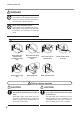
Installing the Machine Step 1 : Deciding on an Installation Site Placement and Installation WARNING Unloading and placement are operations that must be performed by 4 people or more. Tasks that require undue effort when performed by a small number of people may result in physical injury. Dropping the machine may result in injury. The weight of the machine alone is 120 kg (265 lb.). Unload and place the machine with care.
Installing the Machine Never install the machine in a location subject to wide fluctuations in temperature or humidity. Never install the machine in a location subject to shaking or vibration. Never install the machine in a location where the floor is tilted, not level, or unstable. Never install the machine in a dusty or dirty location or outdoors. Never install the machine in a location exposed to direct sunlight or near air-conditioning or heating equipment.
Installing the Machine Step 2 : Removing the Retainers Attach the retainers to protect the machine from vibration during shipment. When installation is complete, remove these and store them in the specified locations. WARNING Carry out these operations before you connect the power cord. The power turning on inadvertently during these operations may result in pinched hands or other injury. I mp o rt an t • Remove all the retainers.
Machine Highlights Features of This Machine This is a cutting machine that supports resin raw materials. Installing the exclusive software on your computer and connecting your computer to this machine enables you to perform high-quality cutting. Also, installing the optional rotary axis unit makes it possible to perform four-axis cutting operations such as multiple-surface cutting. For the latest information on this machine, see the Roland DG Corp. website (http://www.rolanddg.com).
Part Names and Functions Front Front cover If you open this cover, cutting automatically stops for your safety. P. 26 "Emergency Stop or Pause Due to Opening or Closing the Cover" Built-in panel User's manual (electronic-format manual) Emergency stop button Press this in an emergency to turn off the power and stop the machine. P. 25 "Performing an Emergency Stop on This Machine" Dust box cover The dust box is contained within this cover.
Part Names and Functions Spindle head In this document, the mechanisms around the spindle unit, including the spindle motor, are called the "spindle head." Spindle unit Spindle cover Collet ATC magazine Tool sensor Stocker number Stocker Magazine cover Z0 sensor/rotary axis connector This is for connecting a Z0 sensor or rotary axis unit (option). To prevent cutting waste from entering into the connector, attach the protective cap when the connector is not in use.
Part Names and Functions Side Right Side Cable clamp USB connector This is for connecting a USB cable. Power switch Power-cord connector Left Side Alarm lamp attachment location Attach an alarm lamp (commercially available) to the machine here. With the factory default setting, a cover is in place over the connection position. Alarm Lamp Connector Use this to connect an alarm lamp to the machine. With the factory default setting, a cover is in place over the connection position. P.
Performing an Emergency Stop on This Machine Emergency Stop When you press the emergency stop button, operation stops immediately. Canceling an Emergency Stop Procedure A Switch off the power switch. B Turn the button in the direction of the arrows. C Switch on the power switch.
Emergency Stop or Pause Due to Opening or Closing the Cover Emergency Stop Due to Opening or Closing the Cover To ensure safety, opening the front cover or the dust box cover during cutting or spindle rotation causes this machine to perform an emergency stop. Follow the displayed messages to cancel the emergency stop. Canceling an Emergency Stop Procedure A When you close the cover, a message is displayed on the built-in panel.
Emergency Stop or Pause Due to Opening or Closing the Cover Pause Due to Opening or Closing the Cover To ensure safety, opening the front cover or the dust box cover during standby, when operations are paused, or in other situations when the spindle is not rotating will cause the machine to pause its operations and display a message. When you clear the message using the following procedure, the machine will return to the previous screen.
Preparing the Machine for Use Step 1 : Checking the Included Items The following items are included with the machine. Make sure they are all present and accounted for.
Preparing the Machine for Use Step 2 : Installing the Roland DG Software Package What Is the Roland DG Software Package? The following pieces of software are included on the Roland DG Software Package CD. "(*1)" indicates drivers and software that are required for the operation of this machine. Windows Driver(*1) This is a Windows-based driver required for sending data from a computer to the machine. VPanel for MDX-50 (*1) This is the dedicated software for controlling this machine.
Preparing the Machine for Use Installation Procedure You can install the driver, software, and electronic-format manual all at once. You can also install the driver and each piece of software separately. ""User's manual (electronic-format manual) "Installing the Driver Separately" I mp o rt an t • Be sure to connect the machine to the computer as instructed in the procedure. Failure to follow the correct procedure may make installation impossible.
Preparing the Machine for Use Windows 8.1 Click [Install]. Windows 7 Click [Install]. E When the window shown in the following figure appears, click [OK]. F Click [Install], select "Roland MDX-50" for the device name and "USB" for the port, and then click [Start]. The driver installation begins. Follow the on-screen explanations to proceed with the installation. MEMO When the driver installation is complete, the software installation begins.
Preparing the Machine for Use Viewing User's Manuals The documentation for the machine and for the software programs is in electronic format. Follow the procedure below to view these manuals. ""P. 21 "Documentation Included with the Machine" Windows 10 and 7 From the [Start] menu, click [All apps] (or [All Programs]), [MDX-50 Manuals], and then click [User's Manual]. Windows 8.1 On the [Start] screen, click under [MDX-50 Manuals]. .
Preparing the Machine for Use Step 4 : Switching On the Machine's Power Switch (Setting the Panel Display Language) WARNING This procedure makes the machine operate. Before you perform this procedure, check to make sure that operation of the machine will not create any hazard or danger. Procedure A B Close the front cover and the dust box cover. C When the following screen appears, press [MENU] on the built-in panel. "Please hit [ENTER] key." is displayed on the screen.
Preparing the Machine for Use Step 5 : Connecting the Machine to a Computer Using a USB Cable I mp o rt an t • For the USB cable, use the included cable. • Do not use a USB hub. Connection may not be possible. Procedure A Connect the machine to the computer using the USB cable. The driver will be installed automatically. B Secure the USB cable with a cable clamp.
Preparing the Machine for Use Step 6 : Starting VPanel Procedure A B Close the front cover and the dust box cover. Display VPanel. Windows 10 and 7 From the [Start] menu, click [All apps] (or [All Programs]), [VPanel for MDX-50], and then click [VPanel for MDX-50]. Windows 8.1 On the [Start] screen, click . On the [Apps] screen, click the [VPanel for MDX-50] icon under [VPanel for MDX-50]. The top window of VPanel will appear.
Preparing the Machine for Use Step 7 : Performing Spindle Run-in Perform spindle run-in to stabilize the rotation of the spindle. Procedure A Click in the VPanel top window, the [Maintenance] tab, and then click [Spindle...]. The VPanel "Spindle maintenance" dialog box appears. B Click [Start] next to "Run-in." C When the window shown in the following figure appears, click [OK]. Run-in will begin. (It takes approximately 40 minutes.
Preparing the Machine for Use Step 8 : Correcting the Machine (Automatic Correction) Performing automatic correction will correct the ATC magazine and rotary axis positions. Required Items Detection pin 1. A Cloth for care Install the detection pin. Use the included cloth for care to wipe clean the detection pin and the protrusions on the left and right of the ATC magazine. If any dirt is present in these locations, it may not be possible to perform the correction properly.
Preparing the Machine for Use 2. Perform automatic correction. A Click in the VPanel top menu, the [Correction] tab, and then click [Automatic correction]. The VPanel "Automatic correction" dialog box appears. B Select the [Magazine] check box, and then click [Start Correction]. You can use the [Rotary axis unit] check box when you are using the optional rotary axis unit. Automatic correction starts. 38 C When the window shown in the following figure appears, click [OK].
Preparing the Machine for Use Step 9 : Exiting VPanel Procedure A Right-click in the task tray, and then click [Exit]. MEMO Even if you click the Close button ([x]) to close the top window, you will not exit VPanel. Step 10 : Switching Off the Machine's Power Procedure A Switch off the power switch.
Machine Specifications Power Rating and Serial Number Location Serial number The serial number is required for maintenance, servicing, and support. Never peel off the label. Power rating Use a power supply that meets the requirements for voltage, frequency, and amperage given here. Expansion Port Specifications I mp o rt an t Be sure to turn off the power of machine when the cable connect (or remove) to the machine.
Machine Specifications Note Be sure to use the expansion port within the rated range shown above. Do not apply additional voltage to the terminal. Do not short-circuit the terminal to ground. Expansion Port 2 PIN number Signal IN/OUT Overview/function 1 GND Connect this to the power supply GND. 2 Reserve RXD IN This is a spare output for communication. 3 Reserve RXD OUT This is a spare output for communication. 4 N.C. 5 Reserve Out1 OUT This is a spare general-purpose output.
Machine Specifications Female terminal Output specifications Output terminal OUT GND GND EXT Output: Open collector Output capacity: 10 mA max. Input specifications +24 V 3.
Machine Specifications Alarm Lamp Connector PIN number 1 Signal Overview/function 24V Set the output up to 150 mA. 2 ERROR This signal activates when a fatal error occurs. 3 BUSY This signal activates when the machine is operating. READY This signal activates when preparations are complete. 4 (left) (right) Connector layout 2 3 4 Output specifications Use 1 24V as the power supply, and then connect the lamp to 2, 3, and 4.
Machine Specifications Dimensional Drawings Unit: mm (inch) External Dimensions 732 (28.82 ) 620 (24.41) 50 (1.97) 660 (25.98) 1108 (43.62) 760 (29.92) 125 (4.92) 580 (22.83) 900 (35.43) * A space of 700 mm (27.56 inch) in front of the product is required when pulling out the dust box cover.
Machine Specifications 86 (3.39) 4.2 × 7 (0.17 × 0.28) slot ø4.2 (ø0.17) 43 (1.69) 86 (3.39) Y-axis travel 305 (12.01) 86 (3.39) Table 8- ø4.5 (ø0.18), ø9 (ø0.35) countersunk surface 41 (1.61) 10 (0.39) 176 (6.93 ) 216 (8.50) 254 (10) 400 (15.75) X-axis travel Z-axis travel 135 (5.31) 73 (2.87) 130 (5.12) 23.5 (0.93) 19 (0.75) Detection pin 43 (1.69) ø7 (ø0.
Specifications MDX-50 Resins such as chemical wood and modeling wax (metal not supported) X, Y, Z: 400 × 305 × 135 mm (15.8 × 12.0 × 5.3 in.) Cuttable material Operating range Loadable workpiece size Axis drive system Operating speed Mechanical resolution X, Y, Z: 400 × 305 × 100 mm (15.8 × 12.0 × 3.9 in.) Stepping motor X, Y: 7 to 3600 mm/min (0.3 to 141.7 in./min) Z: 7 to 3000 mm/min (0.3 to 118.1 in./min) 0.001 mm/step (0.039 mil/step; RML-1) 0.001 mm/step (0.039 mil/step; NC code) 0.01 mm/step (0.