Before using the XS-1HD, ensure that its system program is at the most recent version. For information on available upgrades for the system program, see the Roland website (https://proav.roland.com/). You can check the system program version by pressing the [MENU] button g “System” g “Version.” Owner’s Manual (this document) Read this first. It explains the basic things you need to know in order to use the XS-1HD.
Contents USING THE UNIT SAFELY. . . . . . . . . . . . . . . . . . . . . 3 IMPORTANT NOTES. . . . . . . . . . . . . . . . . . . . . . . . . . 5 Panel Descriptions . . . . . . . . . . . . . . . . . . . . . . . . . . 6 Top Panel/Front Panel . . . . . . . . . . . . . . . . . . . . . . . 6 Rear Panel/Side Panel (Connecting Your Equipment) . . . 8 Basic Operation. . . . . . . . . . . . . . . . . . . . . . . . . . . . . 10 Turning the Power On/Off. . . . . . . . . . . . . . . . . . . .
USING THE UNIT SAFELY About WARNING and CAUTION Notices Used for instructions intended to alert the user to the risk of death or severe injury should the unit be used improperly. Used for instructions intended to alert the user to the risk of injury or material damage should the unit be used improperly. * Material damage refers to damage or other adverse effects caused with respect to the home and all its furnishings, as well to domestic animals or pets.
USING THE UNIT SAFELY WARNING Do not allow foreign objects or liquids to enter unit; never place containers with liquid on unit Do not place containers containing liquid (e.g., flower vases) on this product. Never allow foreign objects (e.g., flammable objects, coins, wires) or liquids (e.g., water or juice) to enter this product. Doing so may cause short circuits, faulty operation, or other malfunctions.
IMPORTANT NOTES Power Supply Maintenance • Do not connect this unit to same electrical outlet that is being used by an electrical appliance that is controlled by an inverter or a motor (such as a refrigerator, washing machine, microwave oven, or air conditioner). Depending on the way in which the electrical appliance is used, power supply noise may cause this unit to malfunction or may produce audible noise.
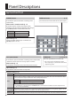
Panel Descriptions Top Panel/Front Panel p. 18 [COLOR] buttons MAIN level meter These buttons operate as follows according to the screen mode. This indicates the volume level of the audio output. Matrix mode / Switcher mode (p. 17) The button applies a fade to the output video, outputting a single-color (background color) image. The [COLOR] button indicates the fade status. Lit red Faded out Blinking red Fading in/out Lit white Normal output Split mode (p. 14) Layers are hidden.
Panel Descriptions p. 21 [MEMORY] button This button turns the memory function on/off. If this is on, up to 16 sets of the video/audio settings and the state of the operation panel can be saved and recalled. 55 Save (lit red); 55 Recall (lit green): p. 17 HDCP indicator This indicator is lit, blinking, or unlit according to the HDCP (copy protection) setting and according to whether an HDCP-compliant device is connected.
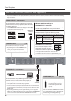
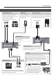
Panel Descriptions Rear Panel/Side Panel (Connecting Your Equipment) * To prevent malfunction and equipment failure, always turn down the volume, and turn off all the units before making any connections. VIDEO OUTPUT 1–4 connectors These connectors output video. You can connect them to devices such as projectors, video recorders, or external displays. * The VIDEO OUTPUT 4 connector displays a menu (OSD) on the connected monitor (p. 10). HDMI input connector When in switcher mode (p.
Panel Descriptions AUDIO OUTPUT jacks PHONES jack RS-232 connector These jacks output the resulting audio mix. Connect them to an audio recorder, amp, or speakers. These are RCA phono-type jacks. Connect headphones to this jack. This is a stereo mini-type jack. A remote-control device (such as a computer that supports RS-232) can be connected here to remotely control the XS-1HD. Audio input jacks RS-232 connector [PHONES] knob This knob adjusts the volume of the headphones.
Basic Operation Turning the Power On/Off * Before turning the unit on/off, always be sure to turn the volume down. Even with the volume turned down, you might hear some sound when switching the unit on/off. However, this is normal and does not indicate a malfunction. Turning the power on Operating the Menu Here’s how to display the menu, and make settings for the XS-1HD itself and for video and audio. * The menu is shown only on the monitor that’s connected to the VIDEO OUTPUT 4 connector. 1.
List of Compatible Video Formats Input Video Formats Output Video Formats Frame Rate Frame Rate When set to “59.94 Hz” When set to “50 Hz” When set to “59.94 Hz” When set to “50 Hz” 480/59.94i 576/50i 720/59.94p 720/50p 480/59.94p 576/50p 1080/59.94i 1080/50i 720/59.94p 720/50p 1080/59.94p 1080/50p 1080/59.94i 1080/50i 1024 x 768/60 Hz 1024 x 768/75 Hz 1080/59.
Video Operations Setting the Output Format Switching Video Here’s how to specify the output format as appropriate for the devices connected to the XS-1HD. Here’s how to switch between the video input signals and output the result. 1. [MENU] button g “Output” g select “Format.” About the Screen Modes The XS-1HD’s video output has three screen modes: matrix, split, and switcher. Matrix mode (next page) 2. Use the [VALUE] knob to select the output format.
Video Operations Switching in Matrix Mode Use the cross-point buttons to switch the combination of four inputs and four outputs, and output the video. The internal frame synchronizer allows seamless video switching. Operating procedure 1. As described in “Switching the screen mode” on the previous page, set the screen mode to Matrix. 3. Press a cross-point button. 2. Use the [TIME] knob to specify the video transition time. The output video is switched.
Video Operations Switching in Split Mode Up to four screens of the video selected by the cross-point buttons can be layer-composited and output. The video of XPT 1 can also be key-composited. Operating procedure Hiding the layers 1. As described in “Switching the screen mode” (p. 12), set the screen mode to Split. 2. Use the [TIME] knob to specify the video transition time. 1. Press the [COLOR] button of the layer whose video you want to hide. The [COLOR] button is lit red. 2.
Video Operations Switching in Switcher Mode The video of the PGM side (XPT3 row) is always output. The PST side (XPT4 row) selects the preset video (the video that will be output next). Use the [AUTO] button or operate the video fader to switch the video. Operating procedure Compositing with PinP or key Here’s how to composite videos using PinP. You can also key-composite the PinP inset video. 1. As described in “Switching the screen mode” (p. 12), set the screen mode to Switcher. 2.
Video Operations Outputting a Loaded Still Image A still image that you load from a USB flash drive can be assigned to an input channel, and output in the same way as video. Supported still image format and resolution You can load still images of the following file format. Format Bitmap (.
Video Operations Fading the Output Video Here’s how to apply a fade to the output video, so that a single color (background color) video is output. * This is available when the screen mode is matrix mode (p. 13) or switcher mode (p. 15). * Fade operations are not possible while the menu is displayed. Close the menu before performing fades. 1. Press the [COLOR] button of the output channel that you want to fade-out. During the fade, the [COLOR] button blinks red.
Audio Operations You can adjust the volume (Level) of audio that is input or output, and change the state (State) of each channel. 1. Press the [MENU] button g select “Audio” to access the Audio menu. Page 1/2 Specifying the State of Each Channel (State) Muting the Audio (Mute) Input channel 1 Input channel 2 Input channel 3 Input channel 4 Output channel Page 2/2 Here’s how to temporarily mute the input audio or the output audio (Mute function). 1.
Other Functions Using Quick Edit to Adjust Video or Audio Quick edit is a function that lets you adjust the video or audio from the operation panel without having to display the menu. Using the Video Quick Edit You can adjust the input or output video’s quality, scaling, and the PinP inset screen’s position and size. The buttons are shortcuts for the following menu items. XPT1 OUTPUT POSITION INPUT POSITION XPT2 OUTPUT COLOR INPUT COLOR PinP VIEW — PinP WINDOW KEY 1.
Other Functions Using the Audio Quick Edit You can adjust the volume (Level) of audio that is input or output, and change the state (State) of each channel. Each button is lit in one of three colors according to the value of the “Level” setting. Input audio level meter (dB) OVER -18 -48 Red Yellow Green The lit color of the buttons indicates the “State” setting.
Other Functions Saving or Recalling Settings (Memory) The current settings for video and audio, together with the state of the operating panel, can be saved in memory as a set and recalled when necessary. The XS-1HD provides 16 memories. Memory 1 functions as “last memory.” With the factory settings, memory 1 functions as “last memory.” When you close the menu or recall a memory, the current settings are automatically saved in memory 1.
Other Functions Saving the XS-1HD’s Settings as a File on a USB Flash Drive The XS-1HD’s memories (1–16) can be saved together as a single file on a USB flash drive connected to the USB MEMORY port. A saved file can be loaded into the XS-1HD from the USB flash drive when necessary. Folder structure When you save the XS-1HD’s settings, a folder is created on the USB flash drive. The created folder contains the XS-1HD’s settings as a file.
Other Functions Formatting a USB Flash Drive The first time that you use a USB flash drive, you must use the XS-1HD to format it. NOTE 55 A USB flash drive that was not formatted by the XS-1HD will not be recognized. 55 Never turn off the power or remove the USB flash drive while the message “Processing.” is shown. 55 Use a commercially available USB flash drive or a USB flash drive sold by Roland. However, we cannot guarantee that all commercially available USB flash drives will work with this unit.
Appendices Block Diagram Video Section Matrix mode INPUT INPUT 11 INPUT INPUT 22 INPUT INPUT 33 INPUT INPUT 44 HDMI HDMI STILL STILL IMAGE IMAGE HDMI HDMI STILL STILL IMAGE IMAGE HDMI HDMI STILL STILL IMAGE IMAGE HDMI HDMI STILL STILL IMAGE IMAGE SCALER SCALER FRAME SYNCHRONIZER FRAME SYNCHRONIZER SCALER SCALER FRAME FRAME SYNCHRONIZER SYNCHRONIZER SCALER SCALER FRAME FRAME SYNCHRONIZER SYNCHRONIZER MIXER MIXER SCALER SCALER FRAME FRAME SYNCHRONIZER SYNCHRONIZER BACKGROUND BACKGROUND Split mode INPU
Appendices SCALER SCALER COLOR COLOR CORRECTOR CORRECTOR HDMI HDMI OUTPUT OUTPUT 11 SCALER SCALER COLOR COLOR CORRECTOR CORRECTOR HDMI HDMI OUTPUT OUTPUT 22 SCALER SCALER COLOR COLOR CORRECTOR CORRECTOR HDMI HDMI OUTPUT OUTPUT 33 SCALER SCALER COLOR COLOR CORRECTOR CORRECTOR HDMI HDMI OUTPUT OUTPUT 44 MENU MENU SCALER SCALER COLOR CORRECTOR CORRECTOR COLOR HDMI HDMI OUTPUT OUTPUT 11 COLOR CORRECTOR CORRECTOR COLOR HDMI HDMI OUTPUT OUTPUT 22 COLOR CORRECTOR CORRECTOR COLOR HDMI HDMI
STILL IMAGE STILL IMAGE INPUT 4 Appendices HDMI BACKGROUND STILL IMAGE SCALER FRAME SYNCHRONIZER BACKGROUND Switcher mode INPUT 1 INPUT INPUT 21 INPUT INPUT 32 INPUT INPUT 43 INPUT 4 HDMI STILL IMAGE HDMI HDMI STILL IMAGE STILL IMAGE HDMI HDMI STILL IMAGE STILL IMAGE HDMI HDMI STILL IMAGE STILL IMAGE HDMI BACKGROUND STILL IMAGE SCALER FRAME SYNCHRONIZER PGM SCALER SCALER FRAME SYNCHRONIZER FRAME SYNCHRONIZER PST PGM SCALER SCALER FRAME SYNCHRONIZER FRAME SYNCHRONIZER CROSSPOINT SCALER SCALER FR
COLOR CORRECTOR COLOR CORRECTOR HDMI HDMI COLOR CORRECTOR HDMI OUTPUT OUTPUT 43 MENU OUTPUT 4 Appendices MENU PGM MIXER PinP KEY MIXER PinP KEY HDMI COLOR CORRECTOR OUTPUT 1 PGM PGM PVW (*1) PGM COLOR CORRECTOR COLOR CORRECTOR HDMI HDMI OUTPUT OUTPUT 21 COLOR CORRECTOR COLOR CORRECTOR HDMI HDMI OUTPUT OUTPUT 32 COLOR CORRECTOR COLOR CORRECTOR HDMI HDMI OUTPUT OUTPUT 43 CORRECTOR (*1) When the Composition menu’s “Mode” isCOLOR set to “PinP & Key.
Appendices Troubleshooting If you suspect a malfunction, please check the following points. If this does not resolve the problem, contact a nearby Roland Service Center. Problem Check Action Page Problems with video Video is not input Video of a format not supported by the XS-1HD is Could the cross-point buttons be unlit? being input. If valid video is being input, the cross- p. 11 point button is lit white. Could you be inputting copy-protected If you want to input copy-protected (HDCP) video, p.
Appendices Main Specifications Roland XS-1HD: Multi-format Matrix Switcher Video Processing Input Connectors Output Connectors Formats Effects Still Image 4:4:4 (Y/Pb/Pr, RGB)/10 bits, 4:2:2 (Y/Pb/Pr)/10 bits HDMI HDMI type A x 4 (HDMI INPUT 1–4) *HDCP Supported HDMI HDMI type A x 4 (HDMI OUTPUT 1–4) *HDCP Supported 480/59.94i (*1), 576/50i (*1), 480/59.94p (*1), 576/50p (*1), 720/59.94p, 720/50p, 1080/59.94i, 1080/50i, 1080/59.
Appendices Dimensions Unit: mm 35 3 117 112 328 313 57 About the POWER Button Cover By attaching the included POWER button cover, you can prevent the [POWER] button from being pressed inadvertently. You can attach it as necessary. 1. Use the two included screws to fasten the POWER button cover as shown in the illustration.
For the U.K. IMPORTANT: THE WIRES IN THIS MAINS LEAD ARE COLOURED IN ACCORDANCE WITH THE FOLLOWING CODE. NEUTRAL BLUE: BROWN: LIVE As the colours of the wires in the mains lead of this apparatus may not correspond with the coloured markings identifying the terminals in your plug, proceed as follows: The wire which is coloured BLUE must be connected to the terminal which is marked with the letter N or coloured BLACK.
For EU Countries For China * 5 1 0 0 0 5 8 5 9 5 - 0 2 *