
User Manual

12
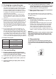
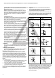
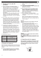
3. Adjusting or exchanging jaws
3.1 To adjust or change the chuck jaws, open with a key
until the display pins are protruding. The toothing
of the appropriate wedge pieces are no longer in
contact with the basic jaws. In this position the
jaws are secured against outwards acceleration by
a locking disc if the machine spindle is unintentio-
nally started. The jaws can then only be adjusted
or exchanged when the locking disc of each jaw is
released by the appropriate pressure pins on the
external diameter of the chuck.
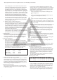
Montage- und Betriebsanleitung für
Fremdsprachentexte ...
Handspannfutter (Keilstangenprinzip)
Fremdsprachentexte ...
Fremdsprachentexte ...
mit Backensicherung
DURO-T
E
F
RUSS
3.2 The jaws can be adjusted equally outwards or in-
wards in series, depending on the desired diameter.
When this is carried out, it must be ensured that the
each basic jaw is pushed in to at least the outer mar-
king grooves so that the entire wedge piece toothing
carries load. Ensure that the numbers on the jaws
match the numbers on the guiding groove on the
chuck body.
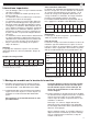
3.3 Jaws must noticeably click and raster into the
chuck body.
3.4 Move the basic jaws as far in as possible using
a key until the display pin disappears, as only
in this position is the wedge piece toothing is
located so that the high clamping forces are
transferred with sufcient safety.
3.5 Just before hitting the stopper the display pins
protrude. Now no more force should be applied,
as further tensioning is not possible.
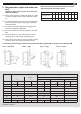
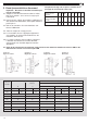
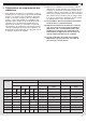
Chuck size Test 3 (rings) Radial runout Test 4 (runout)
Außenspannung Permitted deviation according to Permitted deviation according to
d5 d6 d7 DIN 6386 Röhm factory
standard
DIN 6386 Röhm factory
standard
Jaws UB EB UB EB UB EB
125 - 65 - 95 - 125 0,04 0,02 0,03 0,015
160 90 135 160 170 0,04 0,02 0,03 0,015
200 115 170 200 210 0,06 0,03 0,03 0,015
250 - 165 245 0,06 0,03 0,03 0,015
315 - 205 315 0,08 0,04 0,04 0,02
400 - 255 400 0,08 0,04 0,04 0,02
500 - 335 500 0,10 0,05 0,05 0,025
630 - 477 - 637 - 0,10 0,05 0,05 0,025