
User Manual

11
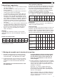
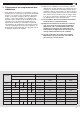
Chuck size 125 160 200 250 315 400 500 630
Tensioning torque
for DURO in Nm
10 40 60 70 80 90 100 100
for DURO-A in Nm - 20 30 35 - - - -
2. Test procedure (axial and radial run-
out)
Important: Only clamp and test the chuck in the
attached condition
2.1 Fit the chuck perfectly according to details in section
1 and only clamp and test it in the attached conditi-
on.
2.2 Use thick-walled test rings for measuring hardened,
precision cylindrical taper check gages and to pre-
vent deformation.
2.3 Use tapered cylindrical tapered check gages with
diameters according to DIN 6386.
2.4 Ensure that written key tensioning torques are follo-
wed.
2.5 The test procedure is also valid for Duro manual
clamping chucks with turned soft capping jaws.
2.6 Values given in the table assume a perfectly running
machine spindle and a properly adjusted chuck.
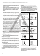
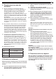
2.7 Checking axial and radial runout accuracy with reversible top jaws (UB) or one-piece reversible jaws EB
Concerning 2.4: Key tensioning torque for control
and wearing axial and radial runout:
Montage- und Betriebsanleitung für
Fremdsprachentexte ...
Handspannfutter (Keilstangenprinzip)
Fremdsprachentexte ...
Fremdsprachentexte ...
mit Backensicherung
DURO-T
E
F
RUSS
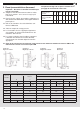
Chuck size 125 160 200 250 315 400 500 630
max. speed
min
-1
6000 5400 4600 4200 3300 2200 1900 1100
Chuck size 125 160 200 250 315 400 500 630
Torque on the key
in Nm
10 40 60 70 80 90 100 100
Total clamping
force kN 1)
8,5 30 48 66 80 95 102 102
Torque on the key
in Nm
40 120 155 190 210 260 320 350
Max. total clam-
ping force in kN
23 73 114 185 240 260 290 320
Continued on page 12
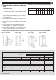
Chuck size Test 1 (mandrels) Test 2 (rings)
Distance Internal clamping
d1 e1 d2 d3 d4
Jaws UB EB UB EB UB EB UB EB UB EB
125 - 25 - 60 - 30 - 60 - 95
160 30 60 70 60 95 140
200 40 80 75 65 100 155
250 53 80 100 180 -
315 75 120 105 210 -
400 100 120 125 265 -
500 100 160 171 311 -
630 125 - 160 - 197 - 354 - -
Test 1 - mandrels Test 2 - rings Test 4 - runoutTest 3 - rings