
Datasheet

10/16
BR25L010-W, BR25L020-W, BR25L040-W, BR25L080-W, BR25L160-W, BR25L320-W, BR25L640-W
Technical Note
At standby
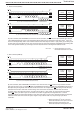
WP cancel valid area
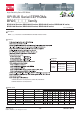
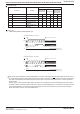
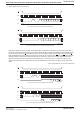
Fig.45 Operating timing
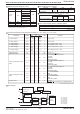
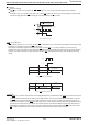
Fig.46 WP valid timing (WRSR)
Fig.47 WP valid timing (WRITE)
CS
SCK
SI
Command start here. SI is read.
Even if CS is fallen at SCL = SI = "H",
SI status is not read at that edge.
012
Ope code Address Data
tE/W
data write time
WP cancel invalid area
WP cancel invalid area
validinvalid
invalid
WP cancel invalid area
Ope code Data
tE/W
data write time
WP cancel invalid areaWP cancel invalid area WP cancel invalid area
CS
SCK
15 16
WP is normally fixed to "H" or "L" for use, but when WP is controlled so as to cancel write status register command and write
command, pay attention to the following WP valid timing.
While write or write status register command is executed, by setting WP = "L" in cancel valid area, command can be
cancelled. The area from command ope code before CS rise at internal automatic write start becomes the cancel valid area.
However, once write is started, any input cannot be cancelled. WP input becomes Don't Care, and cancellation becomes
invalid.
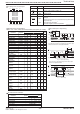
By HOLD pin, command communication can be stopped temporarily. (HOLD status) The HOLD pin carries out command
communications normally when it is HIGH. To get in HOLD status, at command communication, when SCK = LOW, set
the HOLD pin LOW. At HOLD status, SCK and SI become Don't Care, and SO becomes high impedance (High-Z). To
release the HOLD status, set the HOLD pin HIGH when SCK = LOW. After that, communication can be restarted from the
point before the HOLD status. For example, when HOLD status is made after A5 address input at read, after release of
HOLD status, by starting A4 address input, read can be restarted. When in HOLD status, leave CS LOW. When it is set
CS = HIGH in HOLD status, the IC is reset, therefore communication after that cannot be restarted.
HOLD pin
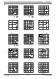
Current at standby
Set CS "H", and be sure to set SCK, SI, WP, HOLD input "L" or "H". Do not input intermediate electric potential.
Timing
As shown in Fig. 45, at standby, when SCK is "H", even if CS is fallen, SI status is not read at fall edge. SI status is read
at SCK rise edge after fall of CS. At standby and at power ON/OFF, set CS "H" status.
2010.07 -
Rev. B
www.rohm.com
© 2010 ROHM Co., Ltd. All rights reserved.