
Datasheet

BD9540EFV
Technical Note
10/17
www.rohm.com
2009.04 - Rev.B
© 2009 ROHM Co., Ltd. All rights reserved.
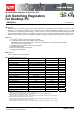
●External Component Selection
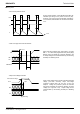
1. Inductor (L) selection
※Passing a current larger than the inductor’s rated current will cause magnetic saturation in the inductor and decrease
system efficiency. When selecting an inductor, be sure to allow enough margin to assure that peak current does not
exceed the inductor’s rated current value.
※To minimize possible inductor damage and maximize efficiency, choose a inductor with a low (DCR, ACR) resistance.
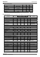
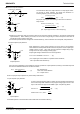
2. Output Capacitor (CO) Selection
Also, give due consideration to the conditions in formula (7) below for output capacitance, bearing in mind that output rise
time must be established within the soft start time frame:
Note: an improper output capacitor may cause startup malfunctions.
3. Input Capacitor (Cin) Selection
A low-ESR capacitor is recommended to reduce ESR loss and maximize efficiency.
ΔI
L=
(VIN-VOUT)×VOUT
L×V
IN×f
[
A
]
・・・
(
3
)
IL=0.3×IOUTmax. [A]・・・(4)
L=
(V
IN -VOUT)×VOUT
ΔIL×VIN×f
[
H
]
・・・
(
5
)
ΔV
OUT=ΔIL×ESR+ESL×ΔIL/TON・・・(6)
Co≦
1ms×(Limit-I
OUT)
V
OUT
・・・
(
7
)
Input Capacitor
I
RMS=IOUT×
VOUT
(
VIN-VOUT
)
VIN
[
A
]
・・・
(
8
)
√
Where VIN=2×VOUT, IRMS=
I
OUT
2
ΔIL
VIN
IL
L
Co
VOUT
Output Ripple Current
VIN
L
Co
VOUT
ESR
Output Capacitor
VIN
L
Co
VOUT
Cin
ESL
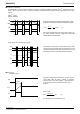
The inductance value has a major influence on output ripple current.
A
s formula (3) below indicates, the greater the inductance o
r
switching frequency, the lower the ripple current.
The proper output ripple current setting is about 30% of maximum
output current.
(I
L: output ripple current; f: switch frequency)
When determining a proper output capacitor, be sure to factor in the equivalent
series resistance and equivalent series inductance required to set the output ripple
voltage to 20mV or more. Also, make sure the capacitor’s voltage rating is high
enough for the set output voltage (including ripple).
Output ripple voltage is determined as in formula (6) below.
(ΔIL: Output ripple current; ESR: CO equivalent series resistance,
ESL: equivalent series inductance)
Tss: Soft start time
Limit: Over current detection
I
OUT : Output current
In order to prevent transient spikes in voltage, the input capacitor selected must
have a low enough ESR resistance to fully support a large ripple current on the
output. The formula for ripple current IRMS is given in equation (8) below:
LG
SW
HG
LG
SW
HG
LG
SW
HG