
Datasheet

Technical Note
7/9
BD52□□G, BD52□□FVE, BD53□□G, BD53□□FVE series
www.rohm.com
2009.06 - Rev.B
© 2009 ROHM Co., Ltd. All rights reserved.
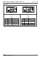
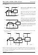
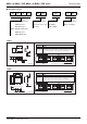
3) Examples of the power supply with resistor dividers
In applications where the power supply input terminal (VDD) of an IC with resistor dividers, it is possible that a through
current will momentarily flow into the circuit when the output logic switches, resulting in malfunctions (such as output
oscillatory state).
(Through-current is a current that momentarily flows from the power supply (VDD) to ground (GND) when the output level
switches from “High” to “Low” or vice versa.)
Fig.21
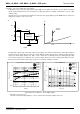
A voltage drop of [the through-current (I1)] × [input resistor (R2)] is caused by the through current, and the input voltage to
descends, when the output switches from “Low” to “High”. When the input voltage decreases and falls below the detection
voltage, the output voltage switches from “High” to “Low”. At this time, the through-current stops flowing through output
“Low”, and the voltage drop is eliminated. As a result, the output switches from “Low” to “High”, which again causes the
through current to flow and the voltage drop. This process is repeated, resulting in oscillation.
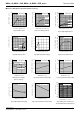
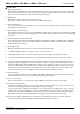
Fig.22 Current Consumption vs. Power Supply Voltage
*This data is for reference only.
The figures will vary with the application, so please confirm actual operating conditions before use.
V
OUT
R2
V
DD
BD52□□
BD53□□
GND
R1
I1
V1
CIN
C
L
IDD
V
DD
VDET
0
Through
Current
VDD - IDD Peak Current Ta=25
°
C
0.001
0.01
0.1
1
10
345678910
VDD[V]
IDD-peak[mA]
BU43xx
BU42xx
BD52xx
BD53xx
Temp - IDD(BD52xx)
0
0.1
0.2
0.3
0.4
-50 -30 -10 10 30 50 70 90 110 130
Temp[
°
C]
IDD peak current [mA]
VDD3V
VDD5V
VDD7V
VDD10V