
Datasheet


Technical Note
7/11
www.rohm.com
2011.03 - Rev.C
© 2011 ROHM Co., Ltd. All rights reserved.
BA□□DD0T Series,BA□□CC0T Series,BA□□CC0FP Series
BA□□DD0WT Series,BA□□DD0HFP Series,BA□□CC0WT Series,BA□□CC0WFP Series
0.0
0.4
0.8
1.2
1.6
2.0
0 25 50 75 100 125 150
Ambient temperature:Ta(
℃)
Power Dissipati on:Pd( W )
0
5
10
15
20
25
0 25 50 75 100 125 150
Ambient temperature:Ta(℃)
Power Dissipation:Pd(W
)
0
1
2
3
4
5
6
7
8
9
10
0 25 50 75 100 125 150
Ambient temperature:Ta(
℃)
Power Dissipati on:Pd( W )
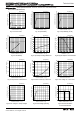
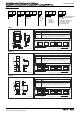
Mounted on a Rohm standard board
Board size : 70×70×1.6 ㎜
Copper foil area :7×7 ㎜
TO252-5θja=96.2(℃/W)
③7.3W
②5.5W
①2.3W
(1)20.0
(2)2.0
1.30
Board size : 70×70×1.6 ㎜
3
(board contains a thermal via)
Board front copper foil area : 10.5×10.5 ㎜
2
①2-layer board (back surface copper foil area :15×15 ㎜
2
)
②2-layer board (back surface copper foil area :70×70 ㎜
2
)
③4-layer board (back surface copper foil area :70×70 ㎜
2
)
When using a maximum heat sick : θj-c=6.25(℃/W)
When using an IC alone : θj-6=62.5(℃/W)
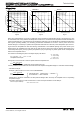
●Thermal Design
HRP-5 TO220FP-5 TO252-5
Fig.29 Fig.30 Fig.31
When using at temperatures over Ta=25℃, please refer to the heat reducing characteristics shown in Fig.29 through 31. The
IC characteristics are closely related to the temperature at which the IC is used and if the temperature exceeds the maximum
junction temperature Tj
MAX., the elements may be damaged or destroyed. From the standpoints of instantaneous destruction
and long-term operating reliability, it is necessary give sufficient consideration to IC heat. In order to protect the IC from
thermal damage, it is necessary to operate it at temperatures lower than the maximum junction temperature Tj
MAX of the IC.
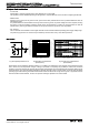
Fig.30 shows the acceptable loss and heat reducing characteristics of the TO220FP package The portion shown by the
diagonal line is the acceptable loss range that can be used with the IC alone. Even when the ambient temperature Ta is a
normal temperature (25℃), the chip (junction) temperature Tj may be quite high so please operate the IC at temperatures
less than the acceptable loss Pd.
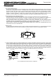
The method of calculating the power consumption Pc(W) is as follows.
Pc = (Vcc-Vo) × Io + Vcc × Icca
Acceptable loss Pd≦Pc
Solving this for load current IO in order to operate within the acceptable loss:
Io≦
(Please refer to Figs.8 and 20 for Icca.)
It is then possible to find the maximum load current Io
MAX with respect to the applied voltage Vcc at the time of thermal design.
・Calculation Example
Example 1) When Ta=85℃, Vcc=8.3V, Vo=3.3V, BA33DD0WT
Io≦ With the IC alone : θja=62.5℃/W → -16mW/℃
Io≦200mA (Icca : 2mA) 25℃=2000mW → 85℃=1040mW
Please refer to the above information and keep thermal designs within the scope of acceptable loss for all operating
temperature ranges.
The power consumption Pc of the IC when there is a short circuit (short between Vo and GND) is :
Pc=Vcc×(Icca+Ishort)
*Ishort : Short circuit current
Pd – Vcc×Icca
Vcc-Vo
1.04-8.3×Icca
5
Vcc:
Vo:
Io:
Vcca:
Input voltage
Output voltage
Load current
Circuit current