
Datasheet

Version 05.00, December 2017
8 Rohde & Schwarz R&S
®
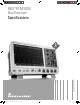
RTM Oscilloscope
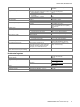
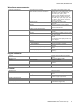
Pattern trigger
trigger events
logic condition between active channels
sources
R&S
®
RTM3002
channel 1, channel 2, logic channels from
D15 to D0 (with R&S
®
RTM-B1 option)
R&S
®
RTM3004
channel 1, channel 2, channel 3,
channel 4, logic channels from D15 to D0
(with R&S
®
RTM-B1 option)
state of channels
high, low, don’t care
logic between channels
and/or
condition
true, false
duration condition
smaller, greater, equal, unequal, inside
interval, outside interval, timeout
minimum duration time
3.2 ns
maximum duration time
6.8 s
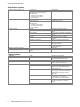
Runt trigger
triggers on pulse of positive, negative or
either polarity that crosses one threshold
but fails to cross a second threshold
before crossing the first one again
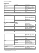
Rise time, fall time
trigger events
time between the crossing of two
selectable levels is smaller, greater, equal,
unequal, inside interval, outside interval
minimum rise time
3.2 ns
maximum rise time
6.8 s
polarity
rising edge, falling edge, both edges
sources
R&S
®
RTM3002
channel 1, channel 2
R&S
®
RTM3004
channel 1, channel 2, channel 3,
channel 4
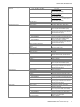
Serial bus trigger
supported standards
R&S
®
RTM-K1 option
I
2
C,
SSPI (two-wire, MOSI/MISO),
SPI (three-wire, MOSI/MISO)
R&S
®
RTM-K2 option
UART/RS-232/RS-422/RS-485 (RX/TX)
R&S
®
RTM-K3 option
CAN/LIN
R&S
®
RTM-K5 option
audio (I
2
S, LJ, RJ, TDM)
R&S
®
RTM-K6 option
MIL-STD-1553
R&S
®
RTM-K7 option
ARINC 429
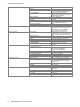
External trigger input
input impedance
1 MΩ ± 1 % with 14 pF ± 2 pF (meas.)
maximum input voltage at 1 MΩ
300 V (RMS), 400 V (V
p
),
derates at 20 dB/decade to 5 V (RMS)
above 250 kHz
trigger level
±5 V
sensitivity
> 300 mV (V
pp
)
coupling
DC, AC, LF reject
Trigger output
functionality
A pulse is generated for every acquisition
trigger event.
output voltage
at high impedance
0 V to 4.8 V
at 50 Ω
0 V to 2.4 V
pulse polarity
high active