
Datasheet

Version 05.00, December 2017
Rohde & Schwarz R&S
®
RTM Oscilloscope 15
Options
R&S
®
RTM-B1
Mixed signal option, additional 16 logic channels
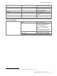
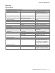
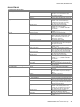
Vertical system
Input channels
16 logic channels (from D15 to D0)
Arrangement of input channels
arranged in two logic probes with
8 channels each, assignment of the logic
probes to the channels D15 to D8 and D7
to D0
Input impedance
100 kΩ ± 2 % || ~4 pF (meas.) at probe
tips
Maximum input frequency
signal with minimum input voltage swing
and hysteresis setting: normal
400 MHz (meas.)
Maximum input voltage
±40 V (V
p
)
Minimum input voltage swing
500 mV (V
pp
) (meas.)
Threshold groups
from D15 to D12, D11 to D8, D7 to D4 and
D3 to D0
Threshold level
user range
±8 V in 25 mV steps
predefined
CMOS 2.5 V, TTL 1.4 V, ECL -1.3 V
Threshold accuracy
±(100 mV + 3 % of threshold setting)
Comparator hysteresis
small, medium, large
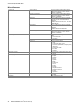
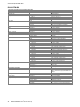
Horizontal system
Channel deskew
range for each channel
±500 ns
Channel-to-channel skew
< 200 ps (meas.) for same vertical settings
on the channels
Acquisition system
Sampling rate
two logic probes
2.5 Gsample/s on each channel
one logic probe
5 Gsample/s on each channel
Memory depth
two logic probes
40 Msample for every channel
one logic probe
80 Msample for every channel
Trigger system
see chapter Trigger system of the base
unit
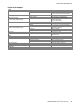
Waveform measurements
Measurement sources
all channels from D15 to D0
Automatic measurements
positive pulse width, negative pulse width,
period, frequency, burst width, delay,
phase, positive duty cycle, negative duty
cycle, positive pulse count, negative pulse
count, rising edge count, falling edge
count
Additional cursor function
display of hex value at the cursor position
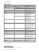
Display characteristics
Channel activity display
independent of the scope acquisition, the
state (stays low, stays high or toggles) of
the channels from D15 to D0 is displayed