
User Manual

Measurements
R&S
®
RTC1000
84User Manual 1335.7352.02 ─ 02
● Fall time (t
f
)
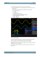
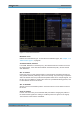
The following measurement values are displayed at the bottom of the screen:
● RMS value
● Peak to peak voltage
● Amplitude
● Pos. pulse width
● Pos. duty ratio
● Period
● Frequency
● Number of positive /slopes
● Neg. pulse width
● Neg. duty ratio
3. Press the QUICK VIEW key again to switch off the function.
The six measurement parameters on the bottom right can be changed using the AUTO
MEASURE key, see Chapter 7.3, "Automatic Measurements", on page 87.
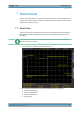
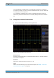
7.2 Cursor Measurements
Cursor measurements are often used with an oscilloscope. Depending on the mea-
surement type, up to three cursor lines are available.
To move cursors:
1. To select the cursor line, press the Universal knob in the Cursor/Menu section.
2. To position the cursor line, turn the Universal knob.
The measurement results are displayed at the bottom of the screen.
If "n/a" is displayed, the measurement is not applicable to the signal. For instance, this
can be the case for a voltage measurement on a "POD" because only logic states with-
out voltage reference are displayed.
If "?" is displayed, the display does not show a complete measurement result. For
instance, the period to be measured is not completely displayed and cannot be identi-
fied.
7.2.1 Cursor Measurement Settings
► Press the CURSOR MEASURE key in the Cursor/Menu section.
Cursor Measurements