
User Manual


Table Of Contents
- R&S NGL200
- Safety Instructions
- Customer Support
- Contents
- 1 Preface
- 2 Welcome to R&S NGL200
- 3 Important Notes
- 4 Getting Started
- 5 Operating Basics
- 6 Instrument Functions
- 7 Remote Control Commands
- Annex
- List of Commands
- Index
Instrument Functions
R&S
®
NGL200
55User Manual 1178.8736.02 ─ 02.01
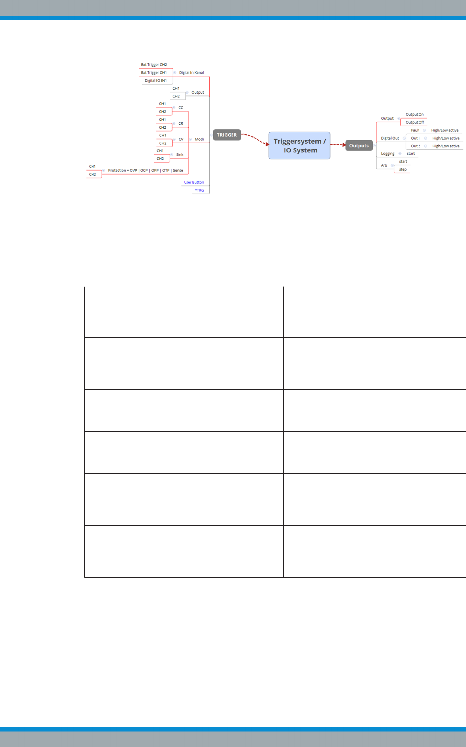
Figure 6-17: Overview of trigger IO system
Red lines = Hardware function
Black line = Software function
Blue = Option is not required for these trigger-in signals
Table 6-1: Trigger-in signals
Trigger-in parameters Source Descriptions
Inhibit Ch1
Inhibit Ch2
Pin 1 of DIO connector
Pin 2 of DIO connector
If detected, respective channel output is turned off
if the inhibit goes active.
Ext trigger Ch1
Ext trigger Ch2
Digital In, pin 2 of DIO
connector
Digital In, pin 10 of DIO
connector
If detected, corresponding trigger-out parameters
are triggered.
See Table 6-2.
In Digital In, pin 3 of DIO
connector
If detected, corresponding trigger-out parameters
are triggered.
See Table 6-2.
Output channel 1
Output channel 2
Output If respective channel output is turned on, corre-
sponding trigger-out parameters are triggered.
See Table 6-2.
CC, CV, CR, Protection, Sink Operation Mode If respective channel output modes, protection
event or sink mode is detected, corresponding
trigger-out parameters are triggered.
See Table 6-2.
User button
*TRG
User button
SCPI command (*TRG)
remotely send to instru-
ment
If detected, corresponding trigger-out parameters
are triggered.
See Table 6-2.
Advanced Features