
User Manual


Table Of Contents
- R&S NGL200
- Safety Instructions
- Customer Support
- Contents
- 1 Preface
- 2 Welcome to R&S NGL200
- 3 Important Notes
- 4 Getting Started
- 5 Operating Basics
- 6 Instrument Functions
- 7 Remote Control Commands
- Annex
- List of Commands
- Index
Operating Basics
R&S
®
NGL200
37User Manual 1178.8736.02 ─ 02.01
5.3.3 Output and Channel Controls
Only applicable for R&S NGL202, these keys control the channel output settings of the
instrument.
Function keys Description
[Ch1], [Ch2] Selects the respective channel for output.
[Output] Toggles the selected channel output on or off.
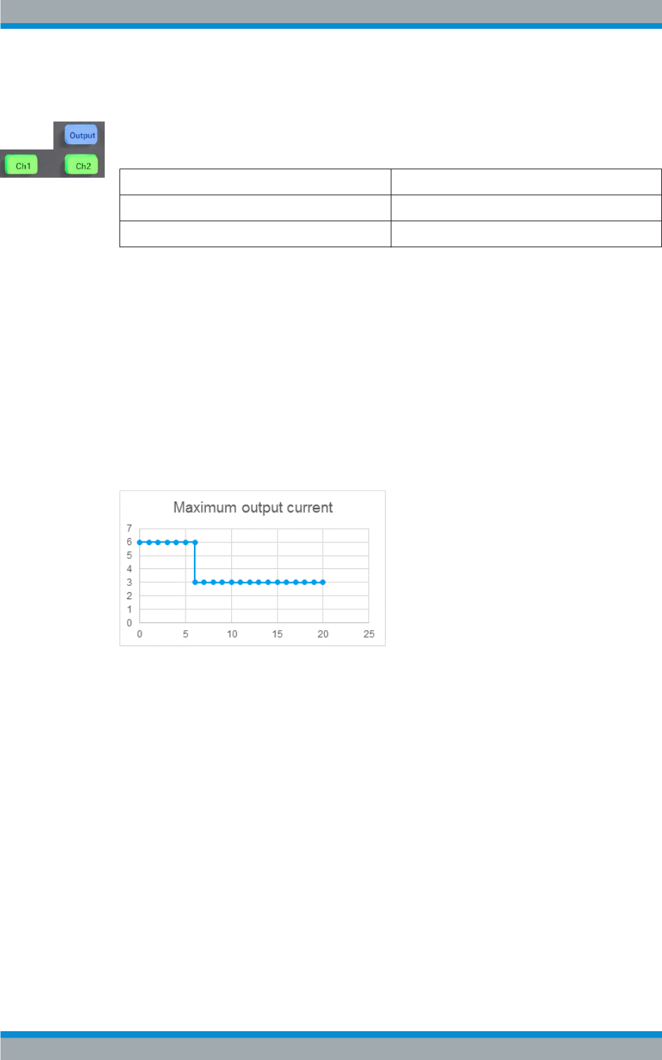
5.4 Power Derating
The NGL202 includes two identical channels with a continuous voltage range of 0 V to
20 V. The instrument provides a source of up to 6 A for voltage below 6 V and 3 A for
voltage range from 6 V to 20 V.
Similar to NGL202, the NGL201 provides a single channel wiith an output power of up
to 60 W.
Combination of the set voltage and current limit results in the following output perform-
ance graph.
Figure 5-9: Output performance graph
5.5 Output Modes
The R&S NGL200 includes three operating modes, i.e. the constant voltage (CV), con-
stant current (CC) and constant resistance (CR). The instrument switches automati-
cally between CV and CC depending on the connected load. In CR mode, the instru-
ment is not switched automatically into sink more. Instead, the instrument operates in
the CR mode (if configured) as soon as it switches from soure mode to sink mode.
CV mode
Figure 5-10 shows that in the range of voltage regulation, the output voltage V
out
remains constant while the current may increase to its maximum value I
max
when the
connected load is increasing. In CV mode, the font text in the channel display area
changes to green.
Output Modes