
User Manual

Instrument Tour
R&S
®
FPC1000
14Getting Started 1178.4124.02 ─ 03
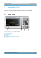
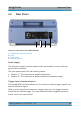
3.2 Rear Panel
1 432
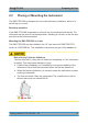
Figure 3-2: Rear panel of the R&S
FPC1000
1 = Trigger input / external reference
2 = LAN
3 = Power supply
4 = USB port (type B)
Power supply
The AC power supply and main power switch are located in a unit on the rear
panel of the instrument.
The main power switch has the following states.
●
Position "1": The instrument is supplied with power.
●
Position "0": The instrument is disconnected from the power supply.
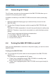
Trigger input / external reference
This female BNC connector allows you to connect an external trigger signal or an
external reference signal.
When you are using the connector as a trigger input, you can trigger measure-
ments with an external trigger. For more information about triggered measure-
ments, refer to the user manual.
Rear Panel