
User Manual

The Spectrum Application
R&S
®
FPC
107User Manual 1178.4130.02 ─ 05
12.7 Trigger Configuration
Access: "Sweep"
Access: "Setup" > "Config Overview" > "Trigger" (selected settings)
Remote commands to trigger measurements:
●
Chapter 17.12.6, "Trigger", on page 251
It often makes sense to capture data only when interesting events occur in the spec-
trum or only capture parts of a signal. In such cases, you can use a trigger. A trigger
responds to certain events. When you use a trigger, the analyzer starts a measurement
only when certain trigger conditions are met.
Selecting the trigger source
The trigger source selects the type of event whose condition must be met to start data
acquisition.
1. Press the "Sweep" key to open the sweep menu.
2. Select the "Trigger" menu item to open the trigger menu.
3. Select one of the trigger sources.
● "Free Run"
No trigger source is considered. You can start the measurement manually any
time and stop it as required.
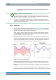
● "Video Trigger"
A measurement starts when the voltage of the video signal exceeds a certain
level.
When you select the video trigger, the R&S FPC opens an input field to define
the trigger level that the video signal must meet or exceed. The video trigger
level is a percentage of the diagram height (0 % to 100 %). A small symbol on
the diagram's y-axis (
) indicates the absolute trigger level.
The video trigger is available for time domain measurements (span = 0). (In the
frequency domain, a measurement would never start with the video trigger
because there is no guarantee that there is a signal that generates video volt-
age at the start frequency.)
● "External Rise" / "External Fall"
A measurement starts on the rising or falling edge of an external trigger signal.
"External Rise": the measurement starts when the trigger signal rises above
1.4 V (a TTL signal level).
"External Fall": the measurement starts when the trigger signal falls below
1.4 V (a TTL signal level).
You can connect the external trigger source to the corresponding BNC connec-
tor on the rear panel of the R&S FPC.
Note that the BNC connector has to be configured as a trigger input in the
instrument setup.
Trigger Configuration