
User guide
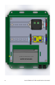
ROGUE TERRAIN OFF GRID POWER SUPPLY ENCLOSURE 5
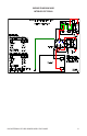
POWER WIRING TEST
Replace the Load fuse in the Load fuseholder.
Replace the Solar fuse in the Solar fuseholder.
Replace the Battery fuse in the Battery fuseholder.
With a multimeter set to a voltage scale that will accommodate 12 VDC,
measure the voltage across the bottom screws of the Battery (+) and Battery
(-) terminals. Then measure the voltage across the Battery and Ground
terminals on the green connector on the left side of the charge controller. The
voltage levels should be the same.
With a multimeter set to a voltage scale that will accommodate 20 VDC,
measure the voltage across the bottom screws of the Solar (+) and Solar (-)
terminals. Then measure the voltage across the IN (+) and Ground (Solar
input) terminals on the green connector on the right side of the charge
controller. The voltage levels should be the same.
Ensure that the Low Voltage Disconnect (LVD) device, if used, is set to the
“On” position. With a multimeter set to a voltage scale that will accommodate
12 VDC, measure the voltage across the bottom screws of the Load (+) and
Load (-) terminals. Then measure the voltage across the bottom screws of the
Battery (+) and Battery (-) terminals. The voltage levels should be the same.
Set the LVD device to the desired low voltage disconnect level.
The Rogue Terrain packaged charge controller is now functional.