INSTRUMENTS LLC W-5000 Contempora ry Keyboa rd User’s Guide
CAUTION RISK OF ELECTRIC SHOCK DO NOT OPEN The lightning flash with arrowhead symbol, within an equilateral triangle, is intended to alert the user to the presence of uninsulated “dangerous voltage” within the product’s enclosure that may be of sufficient magnitude to constitute a risk of electric shock to persons. ! ATTENTION: RISQUE DE CHOC ELECTRIQUE NE PAS OUVRIR CAUTION: TO REDUCE THE RISK OF ELECTRIC SHOCK, DO NOT REMOVE COVER (OR BACK). NO USER-SERVICEABLE PARTS INSIDE.
User’s Guide INTRODUCTION Thank you and congratulations on your choice of the Rodgers W-5000! The W-5000 is a contemporary keyboard instrument which combines the very best of current organ tone-generation and leading-edge synthesizer technology. As a players’ instrument, the W-5000 will satisfy the needs of the most demanding professional, yet is easy enough to operate for the novice player to enjoy. This User’s Guide contains all of the ‘nuts and bolts’ of W-5000 operation.
Rodgers W-5000 Copyright © 1997 RODGERS INSTRUMENTS LLC All rights reserved. No part of this publication may be reproduced in any form without the permission of Rodgers Instruments LLC. Information in this publication is subject to change without prior notice.
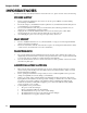
User’s Guide TABLE OF CONTENTS Introduction ...........................................................................................................................................................iii Features..................................................................................................................................................................iii Customer Support .....................................................................................................................
Rodgers W-5000 CHAPTER 4 Effects EFFECTS Section ..................................................................................................................................................50 [MANUAL DRUMS] Button...................................................................................................................50 [UPPER DB VIB] + [LOWER DB VIB] Buttons.......................................................................................51 [DRAWBAR DISTORT] Button......................
User’s Guide CHAPTER 9 Using MIDI Using MIDI ............................................................................................................................................................96 Using External Sound Modules .........................................................................................................................96 Using The W-5000 As A Sound Module ...........................................................................................................
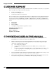
Rodgers W-5000 CUSTOMER SUPPORT The Customer Service Department of Rodgers Instruments LLC is available to answer any of your questions. Before you call, however, please try the following steps: • • • Check your documentation Contact your local Rodgers dealer Call the Rodgers Field Service Department If you are unable to resolve your problem, please feel free to call the Customer Service Department between the hours of 7:00 AM and 5:00 PM Pacific Time, Monday through Friday (excluding holidays).
User’s Guide THE GENERAL MIDI (GM) SYSTEM The General MIDI System is a universal set of specifications for sound generating devices which hasbeen agreed upon by the Japanese MIDI Standards Committee and the American MMA (MIDI Manufacturer’s Association). These specifications seek to allow for the creation of music data which is not limited to equipment by a particular manufacturer or to specific models.
Rodgers W-5000 IMPORTANT NOTES In addition to the Important Safety Instructions inside the front cover, please read and observe the following: POWER SUPPLY • • • • • Before connecting the instrument to other devices, be sure the power to all units is off; this will help prevent damage or malfunction. Be sure the voltage in your installation meets the requirement of your instrument. Check the back panel of your instrument for power requirements.
CHAPTER 1.
Chapter 1 FRONT PANEL DESCRIPTION 5 1 2 3 9 10 4 11 12 6 13 14 15 7 82 16 17 18 19 20 21 22 1 Power Switch This switch turns the W-5000 on and off. 2 Tweeters These are high-frequency speakers.
Introduction & Installation 3 EFFECTS Section These buttons access a variety of the W-5000's effects, such as reverb, chorus, drawbar click, aftertouch and so on. 4 UPPER Tone Select These buttons select Tones and functions for the Upper manual. 5 Music Rest Music rest and panel light intensity can be changed as required. 6 LOWER Tone Select These buttons select Tones and functions for the Lower manual.
Chapter 1 REAR PANEL DESCRIPTION 1 2 3 4 5 6 7 8 9 10 Internal Speaker/Expression Pedal/Pedalboard C t 11 14 12 13 14 15 16 17 18
Introduction & Installation 1 MIXED LINE These XLR connectors allow you to connect your W-5000 to a mixing console BALANCED INPUT (using long cables if necessary). The signal from these connectors is a Line level mix of the individual outputs (SYNTH, DRAWBAR and CLASSIC). 2 RODGERS This is the standard Rodgers connector for the main individual outputs MAIN OUTPUT(SYNTH, DRAWBAR and CLASSIC) and the MIXED LINE or SPKR OUTPUT. It also sends a 'power on' signal to any connected amplifier(s).
Chapter 1 SETUP AND INSTALLATION Because of the W-5000's size and weight, setup and installation are somewhat more involved than with a smaller instrument. Your Rodgers dealer will very likely assist with the delivery and initial setup of your new instrument, and this provides a good opportunity to gain first-hand experience with the process. BASIC ASSEMBLY Your Rodgers dealer may deliver your W-5000 in one piece, or it may be necessary to assemble the two main sections; the keyboard itself and the stand.
Introduction & Installation INSTALLING THE PEDALBOARD Once the instrument is secured to the stand, it will be necessary to install the Pedalboard. First, however, free the two pedal cables that are temporarily secured by a fastener to the underside of the stand. (Do not remove this fastener from the base of the instrument. Before moving the W-5000, be sure that these cables are carefully bundled (without any slack) and secured to the base using the fastener.
Chapter 1 INSTALLING THE PEDALBOARD (W-5000 Version "A" Only) Once the instrument is secured to the stand, it will be necessary to install the Pedalboard. The Pedalboard unit contains two metal hooks which simply hook over top of the short metal bars on the bottom of the stand. (It's very important to make sure the Pedalboard is straight while you firmly push it into its latched position): ¶ Place the Pedalboard against the metal hanger pins on the bottom of the stand.
Introduction & Installation OPENING THE LID The instrument's lid may have been locked for transit. Find the key and unlock the lid. To open the instrument lid, simply lift the handle and fold back. When the lid is folded, push it straight back into the instrument case.
Chapter 1 CONNECTING THE POWER CORD, EXPRESSION PEDAL AND SPEAKERS Be sure the [Power] switch (on the far left-hand side of the panel) is in the OFF position.
Introduction & Installation The speakers, Expression pedal and the Pedalboard must be connected to the keyboard. Find the multi-plug connector (which is located in the channel of the leg) and connect it to the receptacle above and to the left of the MAIN POWER inlet. (See graphic on the previous page.) Once both the power cord and the speaker/Expression pedal/Pedalboard cable are secure, tuck the cables inside the channel and close the cover.
Chapter 1 22
CHAPTER 2.
Chapter 2 POWERING UP Press the [Power] switch.
Performance Basics Ì Press the [+] and [-] buttons in the EDIT section until the LCD is easily readable. (The adjustable range is 0-9.): PANEL / PEDALBOARD LIGHTING The W-5000 contains panel and Pedalboard lights which make it easy to see what you're doing on a dark stage. These lights can be adjusted with the following procedure: Ê Press the [UTILITY] button.
Chapter 2 PERFORMANCE BASICS The W-5000 contains three tone generators; the Drawbar/Tone-Wheel generator (for contemporary organ sounds), the Classic Organ generator (for classical and church organ sounds), and the Synth generator (for synthesized instrument and percussion sounds). The following sections describe how to select and play sounds from these three generators. (If you've worked through the Quick Start guide, you'll already be familiar with these procedures.
Performance Basics Ì Find the [CURRENT DRAWBAR] button in the group of buttons marked UPPER; the button's red LED (Light Emitting Diode) should be lit. (When a [CURRENT DRAWBAR] button is lit, the W-5000's Tone-Wheel generator is active.) UP PE R Í While playing the Upper manual with your right hand, move some of the UPPER drawbars (the sliders with all the numbers on them): As you play, you'll instantly hear that each drawbar affects a different range of the harmonic content of the sound.
Chapter 2 Î Just to the right of the nine UPPER drawbars are two PERC (Percussion) drawbars. Try pushing and pulling these drawbars and you'll notice that they affect the attack or initial portion of the sound, making it a little 'harder' or 'softer'. Ï To add to the fun, find the [ROTARY] button (located on the vertical panel just under the Upper manual). When this button is lit, the W-5000's rotary speaker simulator is active. (This simulates the effect of real rotary speakers such as the famed Leslie.
Performance Basics All of the controls and functions described here (with the exception of the PERC drawbars) are duplicated for the Lower manual (the bottom keyboard). All of the relevant controls for the Lower manual are (cleverly enough) marked LOWER! There are several parameters (settings) which you can set to customize the W-5000's drawbar sounds and rotary effect. Refer to 'Drawbar Parameters' on page 113, and '[ROTARY] Parameters' on page 122 for a complete list of these parameters and what they do.
Chapter 2 Depending on which Tone has been assigned to that button (which you'll learn how to do), the LCD will read something like: This indicates a Program Number ('1' in this case), a Bank Number ('0'), and a name ('Gedackt'). (Note that much of the terminology used with the W-5000's Classic Organ Tones comes from traditional pipe organs.) Play the Upper manual to hear the sound you have selected. Ì To select different Classic Organ Tones (Program Numbers), press the [+] button in the EDIT section.
Performance Basics NOTE: If you've already tried, you've discovered that the drawbars will not affect the Classic Organ Tones. The Classic Organ and Drawbar/Tone-Wheel generators are independent of one another. The drawbars are active ONLY when a [CURRENT DRAWBAR] button is lit. Finally, we come to the last Tone generator in the W-5000, the generator that produces...
Chapter 2 Again, depending on what Tone has been assigned to that button, the LCD might read: Ì Play the Upper manual and you'll hear a piano sound. You might also want to try moving the [Bender/Modulation] lever (just below the [SPKR] knob) while you play. Note that this lever affects all but a few of the Synth Tones available; a simple trial will tell you which. (Drawbar Tones are unaffected by this lever.) + The [Bender/Modulation] lever is one of the W-5000 controllers.
Performance Basics The idea behind the W-5000's structure is that you're able to assign any Tone to any Tone button. So, for example, if you have three favorite piano sounds, you can easily assign each of them to one of the three Piano buttons ([PIANO 1], [PIANO 2] or [PIANO 3]) in a Tone select section. By doing this you'll be able to instantly recall your favorite piano sounds without having to dig through layers of Program and Bank Numbers.
Chapter 2 Î Play the Upper manual to hear the two Tones together. If you'd like to adjust the balance between the two Tones, simply move the UPPER [TONE 1] and [TONE 2] sliders in the BALANCE section (just above the [SPKR] knob). Pulling a slider down will reduce the volume for the corresponding Tone. There are a number of different parameters (settings) that you can set that affect Tone 1 and Tone 2 sounds.
Performance Basics THE SOLO FUNCTION The UPPER and LOWER sections of the W-5000 each contain a [SOLO] button. When this function is active (the button LED is lit), an additional Tone is enabled, which can be restricted to following a single note, or arpeggiating a chord. In effect this gives you three Tones playable from each manual. Balance among the three Tones of either manual can be adjusted using the corresponding sliders ([TONE 1], [TONE 2] and [SOLO]) in the BALANCE section.
Chapter 2 Arpeggio Modes The seven Arpeggio modes are an extension of the W-5000's Solo function. The delay time between the arpeggiated notes or chords is determined by the Vibrato rate. Arpeggio sequences may also be 'latched' using the Sustain pedal. These Arpeggio modes are: Sequence : Notes played are played back, one at a time, in the same sequence (order) they were played in. Up : Notes are played back, one at a time, in ascending order.
Performance Basics BASS TONES PEDALBOARD No serious players' instrument of this type would be complete without a Pedalboard! And the W-5000's is as versatile as the rest of the instrument. The BASS Tone select section allows you to select a variety of Tones for the Pedalboard. Again, you can layer Tones (using the [TONE 1/TONE 2] button) and create the appropriate balance using the BASS [TONE 1] and [TONE 2] sliders in the BALANCE section.
Chapter 2 The Lower manual will be divided or split into two sections: Ë Pressing the [+]/[-] or [++]/[--] buttons in the EDIT section allow you to move the split point on the Lower manual. Use these buttons to set the desired split point. Ì Now you can select and layer Tones for the keybass section using the same procedure described for the Upper and (complete) Lower manuals. The Tone(s) previously selected for the Lower manual will now only apply to the section to the right of the split point.
Performance Basics In addition to all of its great Classic Organ, Drawbar/Tone-Wheel and Synth Tones, the W-5000 contains a wide variety of percussion sounds. These sounds are organized into Drum Sets and are easily selected. Ê Press the [MANUAL DRUMS] button in the EFFECTS section (on the far left-hand side of the panel) : Ë Play the Lower manual (towards the left) and you will hear that a different percussion sound has been assigned to almost every key.
Chapter 2 NOTE: As a default setting, the USER [2] drawbar has been assigned as a volume control for the Manual Drum sounds. Î Press [MANUAL DRUMS] again to return to playing standard Tones across the entire Lower manual. If you refer to page 117 you'll find the '[MANUAL DRUMS] Parameters'. All the parameters that relate to Manual Drums are listed there. See page 146 for a list of the available Synth Drum Sets and the sounds they contain.
CHAPTER 3.
Chapter 3 ADVANCED PERFORMANCE FEATURES Now that you've had a little hands-on experience, you should have a good understanding of the W-5000's basic operation. In this chapter, however, we'll move on to describe some of the instrument's more advanced features. TONE MAPPING The W-5000 contains three 'Tone Maps' (collections or arrangements of sounds): Organ, Synth and PR-300. The Organ Tone map contains the Classic Organ Tones. You select this map automatically whenever you press one of the Organ buttons.
Advanced Performance Features Each Program Number represents a basic instrument sound and the Bank Number represents a variation of that basic sound. For example, if you press the [PIANO 1] button in the UPPER section (which normally selects the PR-300 Tone Map), the display will read: The Tone ‘Piano 1’ is found at Program Number 1 and Bank Number 0 in the PR-300 Tone map. This Tone is assigned to the [PIANO 1] button at the factory.
Chapter 3 OK, suppose you want to assign the Tone 'Hyper Alto' to the [PIANO 2] button in the UPPER Tone select section: Ê Press the [PIANO 2] button in the UPPER section. Ë Select the Tone 'Hyper Alto' (Program Number 66, Bank Number 8 in the Synth Tone map). Do this by pressing the [++] button (which moves you in jumps of eight) until you reach Program Number 65, then increase the Program Number to 66 by pressing the [+] button. Now press [NEXT] to move the cursor to the Bank field.
Advanced Performance Features In the UPPER section (be sure any Tone select buttons are turned off): Ê Press the [CURRENT DRAWBAR] button. Ë Play the Upper manual and adjust the UPPER and PERC drawbars to your liking. Ì Press and hold [DRAWBAR PRESET A] and then press the [CURRENT DRAWBAR] button. All of the current drawbar settings are now stored under the [DRAWBAR PRESET A] button and can be recalled at any time.
Chapter 3 Expression pedal is activated (i.e. moved and held to the left). The [HOLD] button also allows note latching when in arpeggio modes (page 36). Left ‘kick’ switch (footswitch) controls the Hold function. Right ‘kick’ switch (footswitch) controls rotary speed. * Some instrument sounds - like acoustic piano or acoustic guitar - cannot be sustained indefinitely. When using the Hold function with sounds of this type, the notes will sustain for a short time and then decay slowly.
Advanced Performance Features [SUSTAIN] BUTTON (BASS) When on (the button LED is lit), this function adds a release time to the Drawbar and Synth Bass notes played. This function affects both the Keybass section and Pedalboard Tones. Ê Press the [SUSTAIN] button (in the BASS section). Ë Set the release time (0-10) with the [++]/[--] or [+]/[-] buttons. (Higher numbers produce a longer sustain time.
Chapter 3 48
CHAPTER 4.
Chapter 4 EFFECTS SECTION The 10 buttons in the EFFECTS section control a number of effects and special performance functions. When an EFFECTS section button is pressed, the LCD will instantly show the current setting or value for the first parameter of that effect. When the value is displayed, the [+] and [-] buttons in the EDIT section can be used to change the value or setting. Keep in mind that some effects may have several parameters.
Effects [UPPER DB VIB] + [LOWER DB VIB] BUTTONS These buttons (one for each manual) add low frequency modulation to the Upper and Lower Drawbar Tones to simulate Tone-Wheel type vibrato effects. (These buttons turn the effect on and off.) There are several settings you can make for this effect. Note that the same setting must be made for both the Upper and Lower manuals. As that is the case, changing one setting automatically changes the other.
Chapter 4 [DRAWBAR CLICK] BUTTON One of the things that made those old Tone-Wheel organs sound so unique was the keyswitch noise. Pressing the [DRAWBAR CLICK] button on the W-5000 allows you to add that distinctive quality to your own sound: Ê Press the [DRAWBAR CLICK] button (so the LED lights). Ë With the [+] and [-] buttons, set the 'Filt Cutoff' point (0-127). (This controls the overall brightness of the effect.
Effects Ê Select a Tone 1 and Tone 2 sound for the Upper manual. (Selecting Tones which have a very different character will highlight the effect.) Ë Press the [CROSSFADE] button (so the LED lights). Ì Select 'Upper' as the keyboard. (Use the [+] button if it isn't already selected.) Í Press [NEXT] until the word 'Mode' appears and press [+] to select 'Switch'. Î Play the Upper manual softly and you should only hear Tone 1. Gradually play harder and harder. At some point you'll only hear Tone 2.
Chapter 4 [GENERAL REVERB] BUTTON Reverb is a digital effect which creates the illusion that you're playing in spaces of different sizes (like a concert hall or room, for example). That is, the sound decays naturally over time. Pressing the [GENERAL REVERB] button allows you to select the reverb time (which applies to all Tones): Ê Press the [GENERAL REVERB] button (so the button LED lights). Ë Press [NEXT] as necessary to select the 'Time' parameter.
Effects [TRANSPOSE] BUTTON The transpose function allows you to shift (raise or lower) the pitch of both manuals and the Pedalboard: Ê Press the [TRANSPOSE] button (so the button LED lights). Ë Use the [+] and [-] buttons to raise and lower the pitch. The range is: C#-1-B0. (You can also hold the [TRANSPOSE] button (in the 'on' position) and press a key relative to Middle 'C' to set the transposition value.
Chapter 4 Ë Press [NEXT] (as necessary) until the words 'Tw Rise Time' appear. (This parameter allows you to set the time it takes for the tweeter rotation speed to reach maximum from its minimum speed. Parameters for setting the minimum and maximum speeds are also available.) Ì Set the rise time (0-9) with the [+]/[-] buttons. (Higher numbers create a longer rise time.
CHAPTER 5.
Chapter 5 GENERAL PRESETS Along the front edge of the instrument - between the Upper and Lower manuals - is a series of 11 buttons (ignore [ROTARY] and [FAST/SLOW] for the moment). There are eight General Preset buttons ([1]-[8]; also called 'Pistons'), a [SET] button, a [MEMORY] button and a [CANCEL] button: Each button allows you to store (and later instantly recall) all the panel settings that define the sound of the instrument (minus a few global settings, described later).
General Presets Ê Make all the necessary panel settings (Tone assignments, effects settings and function settings) until everything sounds just right. Ë Be sure the [MEMORY] button is on or off, depending on which bank of registrations you wish to work with. (When lit, the second memory bank is active.) Ì Hold the [SET] button and then press the General Preset button ([1]-[8]) you want to use.
Chapter 5 PRESET STORAGE The W-5000 contains several functions which allow you to save, load and protect important data. These functions - accessible through the [PRESETS] button in the FUNCTIONS section - are discussed here. Note that the various Reset functions require that the 'Preset Lock' switch be set to 'Off' (otherwise these operations will not be possible).
General Presets Presets Reset Memory (+) This function resets the eight registrations in the currently selected memory to their factory defaults. It overwrites the eight 'files' in the internal, non-volatile memory with their factory defaults, and loads them into the General Preset buttons. Ê Be sure the [MEMORY] button is on or off, depending on which bank of registrations you wish to reset. Ë Press the [PRESETS] button in the FUNCTION section.
Chapter 5 Presets Reset Lock: On, Off This function allows you to lock the Reset functions so that they cannot be activated by accident: Ê Press the [PRESETS] button in the FUNCTION section. Ë Press [NEXT] (as necessary) until the words 'Reset Lock' appear in the LCD. Ì Press the [+]/[-] buttons to turn the lock 'On' or 'Off'. Presets Auto Load: On, Off This function tells the W-5000 whether or not to select and load a folder when a floppy disk is inserted or removed from the disk drive.
General Presets Ë Press [NEXT] (as necessary) until the words 'Read Globals (+)' appear in the LCD. Ì Press the [+] button to load the global settings. Presets Save Globals (+) This allows you to save the global settings to a floppy disk. Ê Press the [PRESETS] button in the FUNCTION section. Ë Press [NEXT] (as necessary) until the words 'Save Globals (+)' appear in the LCD. Ì Press the [+] button to save the global settings.
Chapter 5 64 Ê Press the [MEMORY] button, to display the currently selected folder. Ë Press the [+]/[-] buttons to select the folder you wish to delete. Note that you cannot delete the Internal folder. Ì Press the [PRESETS] button in the FUNCTION section. Í Press [NEXT] (as necessary) until the words 'Delete Folder (+)' appear in the LCD. Î Press the [+] button to turn the folder 'On' or 'Off'.
CHAPTER 6.
Chapter 6 VOICING AND CONTROLLER SETTINGS Your W-5000 contains a number of controllers; physical controls that you use to play and manipulate sound. In this chapter we'll tell you how you can change the settings for these controllers and even assign different functions to them if you like. We'll also discuss how you can edit (change the basic character of) the instrument's Synth sounds. Before we begin with Controller and Voicing settings, however, let's look at a more basic setting.
Voicing & Controller Settings CONTROLLERS Controllers are the physical controls on the instrument (such as the [Bender/Modulation] lever or the right kick switch) that you can use to manipulate or control the sound as you play. Basically there are two kinds of controllers; continuous and switched. A continuous controller (like the [Bender/Modulation] lever) can produce a continuous or smooth change in the sound from the controller's zero (off) position all the way to its maximum setting if you want.
Chapter 6 controller is at its maximum position. Basically this gives you a two-level control system, not unlike the Gain and Master Gain controls on some amplifiers, for example. The available destinations (and setting ranges) are: Mappable Destinations Values Voicable Destinations Values Switchable Destinations Values Pitch (semitones)* Volume Vib Depth Vib Rate Cutoff Resonance Attack Decay Release Pan Seq Volume Drum Volume Detune (in 'cents') Hz Detune (x 0.
Voicing & Controller Settings SETTING THE CONTROLLERS The best way to understand what all of this means is to try an example. Once you've done that you'll see what we mean! In the LCD, [CONTROLS] parameters are presented in five fields: one for keyboard selection, layer selection, controller selection, destination selection and finally for a depth value: 3 2 1 4 5 OK, suppose you want to be able to control the pitch of Tone 1 in the Upper manual using the USER [1] slider.
Chapter 6 VOICING The Voicing parameters are provided for those who wish to customize the W-5000's Synth or Drawbar Tones. The available voicing parameters are as follows: Keyboards: Layers: Upper, Lower, Pedal, All Tone 1, Tone 2, Drawbar, MIDI, Solo, All Mappable Destinations Values Voicable Destinations Values Switchable Destinations Values Volume Vib Depth Vib Rate Cutoff Resonance Attack Decay Release Pan Seq Volume Drum Volume Detune (in 'cents') Hz Detune (x 0.
Voicing & Controller Settings Í Press [NEXT] to move to the next field. With the [++] and [--] buttons select 'Release' (the destination). Î With the [+] and [-] buttons, set the value to '10' (the maximum value). (Negative numbers in the value field will actually 'clip' the sound you play to make it very short.) Now as you play the Lower keyboard you'll hear that the notes you play have a very long release time; that is, they decay very slowly over time.
Chapter 6 72
CHAPTER 7.
Chapter 7 THE FLOPPY DISK DRIVE Your W-5000 includes a 3.5" floppy disk drive (located just above the LCD): This drive can be used to play commercially available song data (GM/GS Format/SMF data), record your keyboard performances, or store W-5000 data (General Preset or Global data).
The Floppy Disk Drive • Floppy disks contain a 'write protect' tab which protects your data from accidental erasure. To preserve your data, keep the tab in the 'PROTECT' position. Move the tab to the 'WRITE' position only when you wish to add new data to the disk: WRITE PROTECT Protect Tab This protect tab, along with the 'Lock' parameters (found under the [PRESETS] button) help protect your valuable data from accidental erasure. • • • All important data should be copied onto backup disks.
Chapter 7 To remove a disk from the drive, press the Eject button firmly. Do not use excessive force to remove a disk lodged in the drive: • • • Never attempt to remove a disk from the drive while the drive is operating (the activity LED is lit); this could result in damage to both the disk and the drive. Unless specifically instructed to do otherwise, always remove any disk from the drive before powering the instrument up or down.
The Floppy Disk Drive USING THE SEQUENCER LISTENING TO A SONG ON DISK A sequencer is simply a special kind of recording device for MIDI instruments. This same sequencer can also play commercially available song data. The W-5000's sequencer controls are found in the SEQ (Sequencer) section under the LCD: If you have song data on a disk and you'd like to hear it, follow this procedure: Ê Insert the disk into the drive (label side up; metal shutter first).
Chapter 7 PLAYBACK CONTROLS PAUSE You can temporarily pause playback by pressing [PLAY]. Press [PLAY] again to resume playback. STOP If you press [STOP], playback will stop and the song will be reset to the beginning. SEQUENCE TEMPO It's possible to change the playback tempo of a song while playback is in progress (or before playback begins). Use the [NEXT] and [PREVIOUS] buttons (as necessary) to select the tempo screen: Use the [+] and [-] buttons to change the playback tempo (34—312 beats per minute).
The Floppy Disk Drive SEQUENCE CHANGE TEMPO When activated, this function sets the tempo of the current sequence to the value set under the Sequence Tempo parameter value. Press the [+] button to activate this function. SEQUENCE CHANNEL VOLUME It's also possible to make individual volume adjustments for each channel.
Chapter 7 RECORDING YOUR PERFORMANCES The W-5000's sequencer allows you to make recordings of your own keyboard performances. Be aware, however, that this unit is only capable of 'single-pass' recording; you can't go back and add more things to your performance. (For information on multi-track recording, please refer to page 105.) Ê Insert a formatted disk into the drive. (Be sure the disk's protect tab is set to 'WRITE'.) Ë Press the [SEQ] button.
The Floppy Disk Drive STORING W-5000 DATA ON DISK REGISTRATIONS As explained in Chapter 5, General Presets, all the panel settings that define the sound of the instrument can be collected together into a 'registration' and assigned to a General Preset piston ([1]-[8]) for instant recall. There are two banks of these presets, selectable via the [MEMORY] button. One final registration can be assigned to the [CANCEL] button giving a total of 17 registrations.
Chapter 7 AUTOMATIC FOLDER LOADING The [PRESETS] menu contains an Auto Load function, mentioned earlier, which can be set to 'On' or 'Off'. When on, the W-5000 automatically tries to load folder number one whenever a disk is inserted into the drive. If the disk doesn't have folder number one, the internal folder remains active. Similarly, when the disk is removed from the drive, the internal folder is automtically selected. When this function is off, inserting or removing a disk has no effect.
The Floppy Disk Drive • When you execute the 'Write Globals' function ([PRESETS] menu), the global settings are written to the global file in the internal, non-volatile memory. They will therefore be activated next time the instrument is turned on. • When you execute the 'Save Globals' function ([PRESETS] menu), the global settings are written to the global file on disk. This saves the current settings, not a copy of the internal global file.
Chapter 7 84
CHAPTER 8.
Chapter 8 THE AUDIO SYSTEM Although you've no doubt discovered that the W-5000's internal sound system is extremely capable, there may be situations in which you need greater volume or flexibility. You'll be pleased to know that the W5000 is designed to accommodate! NOTE: Before making any connections or disconnecting any cables, be sure all of the equipment in your audio system is off. This includes all mixers, amps, PA systems and the W-5000 itself.
Audio containing the Drawbar sounds after they are routed through the [DRAWBAR DISTORT] and [ROTARY] effects. For the best results, use both the Left and Right jacks. CLASSIC OUTPUT These 1/4" jacks allow you to send a line-level signal from the Classic Organ generator to separate channels of a mixing board, a dedicated effects unit and/or to separate speaker enclosures. This gives you full control over the output of Classic Organ sounds. For the best results, use both the Left and Right jacks.
Chapter 8 INPUTS AUX INPUTS (XLR) These XLR connectors allow you to connect a variety of external devices to your W-5000. These include other keyboard instruments, mixing consoles or microphones. The signals input to the W-5000 can be routed through the on-board reverb unit and then directed to one or more of the output connectors. AUX INPUTS (1/4") These extremely versatile 1/4" jacks accept connection of a wide variety of devices including external sound modules, electronic instruments or microphones.
Audio Audio Org Spkr Mix: 0-127 This parameter allows you to determine the level of the Classic Organ sounds in the overall Speaker mix. Press [NEXT] as necessary until this parameter appears in the LCD. Set the volume level with the [+]/[-] (or [++]/[--]) buttons. Audio DBar Spkr Mix: 0-127 This parameter allows you to determine the level of the Tone-Wheel/Drawbar sounds in the overall Speaker mix. Press [NEXT] as necessary until this parameter appears in the LCD.
Chapter 8 Audio Aux Left RevSnd: 0-127 This parameter allows you to send the signal from the left AUX INPUT to the W-5000's internal reverb unit. Press [NEXT] as necessary to select this parameter. Set the reverb send level with the [+]/[-] (or [++]/[--]) buttons. Audio Aux Right RevSnd: 0-127 This parameter allows you to send the signal from the right AUX INPUT to the W-5000's internal reverb unit. Press [NEXT] as necessary to select this parameter.
Audio AUXILIARY INPUTS Any source that you connect to the AUX INPUTs can also be sent to the Line mix if you so wish. If we continue to use our example of the two microphones, there are a number of parameters that you can set for the Line mix.
Chapter 8 AUDIO SYSTEM CONFIGURATIONS The following few pages present some recommended audio system setups using the W-5000 and a variety of external Rodgers devices. Three setups are illustrated, each targeted at spaces of differing sizes (small, medium and large). Keep in mind that these are suggestions only. To create a system which is customtailored to your particular needs, please consult your Rodgers dealer.
Audio MID-SIZED AUDIO SETUP For situations which require greater volume, adding a Leslie cabinet to the basic setup will not only give you that increased volume, but it will also give you that unique sound quality of a real rotary speaker; Drawbar sounds can be taken from the Spkr or Line mix, or the real rotary sounds from the Leslie can be 'paralleled' with the W-5000's simulated rotary sounds: 93
Chapter 8 LARGE AUDIO SETUP If you're using the W-5000 in situations where high volume levels (and wide sound dispersion) are required, the setup illustrated below is an option to consider. Three pairs of FR 1.7s (one for each of the individual outputs; DRAWBAR, CLASSIC and SYNTH) and a pair of FR 5.0s (for the LINE mix) all driven by four S200 amplifiers should provide all the power you need. (An Audio Cable Interface (Rodgers part number 5298-300) will be necessary to distribute signals.
CHAPTER 9.
Chapter 9 USING MIDI MIDI stands for 'Musical Instrument Digital Interface' - an industry-wide standard that allows electronic musical instruments and computers to exchange musical and system data. Most electronic instruments sold these days are MIDI compatible. MIDI devices have unique, multi-pin connectors which are used to physically link one device to another via special MIDI cables.
Using MIDI For this example, we'll use the Upper manual to trigger sounds in the module. Sounds from the module will then be sent to the W-5000 where they will be played through the internal speakers. Refer to your sound module's manual for information on using it in this type of setup. The [MIDI] buttons in each of the three sections (UPPER, LOWER and BASS) control whether or not note data is sent to the external module (they function as ON/OFF switches).
Chapter 9 USING THE W-5000 AS A SOUND MODULE While it may not seem to be practical (given the instrument's size and weight), it is possible to use the W5000 as a sound module for other devices! To setup for this type of arrangement, connect the MIDI OUT port on the external sequencer or keyboard to either of the W-5000's MIDI IN ports.
Using MIDI MIDI Mst In Filt U: None, PC, CC, CC+PC, Note, PC+Note, CC+Note, All This parameter determines what type of data will be filtered out of the incoming data via the Master MIDI Input for the Upper section.
Chapter 9 EXTERNAL SEQUENCING As the W-5000's sequencer is only capable of 'single-pass recording', you'll need to use an external sequencer if you want to do any multi-track recording. The Rodgers PR-300S is a very good example of such a unit! The following explanation therefore assumes that you're using a PR-300S (or similar unit). (Refer to your sequencer's manual for information on multi-track recording.
Using MIDI First, however, quickly review the parameters described in 'Using The W-5000 As A Sound Module' (page 94). Some of those same parameters will be useful to you. To get you started, here a few parameters you'll need to set: MIDI Mst Out Port: 1, 2 This parameter determines which port (1 or 2) is used as the Master MIDI Output. Data played on the instrument is sent from the selected port. Press [NEXT] to select this parameter. Use the [+]/[-] buttons to choose port '1'.
Chapter 9 commands are received. If set to 'PC', only the General Preset selection is sent. If set to 'CC', only the position of the controllers is sent. If set to 'Both', both the General Preset selection and the controller positions are sent. This way, the start of the song on playback will always set the instrument up the way it was when the song was recorded.
Using MIDI Ì Set (or verify) the following parameters on the W-5000: MIDI Mst In Port 2 MIDI Mst In Chn U:13 L:12 P:14 MIDI Mst In Filt U:None MIDI Mst In Filt L:None MIDI Mst In Filt P:None MIDI Mst In Exp CC#: 7 MIDI Mst Out Port 2 MIDI Mst Out Chn U:13 L:12 P:14 MIDI Mst Out Filt U:All MIDI Mst Out Filt L:All MIDI Mst Out Filt P:PC MIDI Mst Out Exp CC#: 7 MIDI Start Stat Send CC MIDI Local Cntl Upper Off MIDI Local Cntl Lower Off MIDI Local Cntl Pedal On You can use the BASS [MIDI] button to control so
Chapter 9 Ò Change the following parameters on the W-5000: MIDI Local Cntl Lower MIDI Local Cntl Upper MIDI Mst Out Filt MIDI Mst Out Filt Off On U:PC L:All You can use the UPPER [MIDI] button to control sound coming from the PR-300S. Just be sure that its Port is set to '1' and its Channel is '1-10'. Ó Record the third pass by pressing [RECORD] on the PR-300S and playing your Upper manual parts.
Using MIDI you can do is to try to record on fewer layers at any one time, or use simpler sounds with fewer control mappings. Since all MIDI channels are used for Native Mode sequencing, it's essential that it use the MIDI port that isn't used for Master Channel input or output, or for the external MIDI layers. We suggest using MIDI port 1 for these purposes and reserving MIDI port 2 for Native Mode sequencing.
Chapter 9 You might want to redirect certain channels so that something recorded on one channel is sent to another during playback. You can achieve this with some limitations: • Channels 1, 2, 3, 6, 7, 8, 13 and 14 may only be used for Synthesizer and Classic Organ sounds. • Channels 4, 9 and 15 may only be used for Drawbar sounds. • Channels 5, 11 and 16 may only be used for external MIDI sound module control. • Channel 10 may only be used for drums. • Channel 12 is reserved for global controls.
Using MIDI aware, however, that Start and Continue messages are treated in the same way, and that a Stop message activates the pause function. Two Stop messages in a row, however, reset the sequence to the beginning. MIDI Sync Out Port: Off, 1, 2, Both This parameter tells the W-5000 from which port (or ports) to transmit MIDI Clock, Start, Continue and Stop messages. Clock messages are transmitted even while the internal sequence isn't playing so that an external sequencer can monitor the tempo.
Chapter 9 If you also want to hear the W-5000 while you're playing, be sure that the three local control parameters are set to 'On'. If you do not want to send W-5000 General Preset selections to the other Rodgers organ, set the three Mst Out Filt parameters to 'PC'. For a complete list of MIDI parameters please refer to page 113. (MIDI Master parameters are listed on page 133.
CHAPTER 10.
Chapter 10 PARAMETER LISTS The following section contains a list of all the W-5000's parameters. These parameters allow you to configure your instrument in precisely the manner you wish, as they cover everything from chorus and reverb settings, to MIDI settings, to panel light adjustments. Each sub-section contains the parameters found under the corresponding panel button. Buttons are grouped as they appear on the panel.
Appendix UPPER/LOWER/BASS SECTIONS [TONE] Parameters These parameters apply to Tone 1 and Tone 2 sounds. They can be accessed in the LCD whenever you press a Tone button: Prg: 1-128 Bnk: 0-127 Tone Name The first parameter allows you to select the desired Program (Prg) Number. Pressing the [+] and [-] buttons allow you to move through all 127 Program Numbers. (The [++]/[--] buttons advance/move backward through the numbers eight at a time.) Press the [NEXT] button to select the Bank (Bnk) field.
Chapter 10 [SOLO] Parameters These parameters allow you to select and modify the Solo Tone when the [SOLO] button is pressed: Prg: 1-128 Bnk: 0-127 Tone Name The first parameter allows you to select the desired Program (Prg) Number. Pressing the [+] and [-] buttons allow you to move through all 127 Program Numbers. (The [++]/[--] buttons advance/move backward through the numbers eight at a time.) Press the [NEXT] button to select the Bank (Bnk) field.
Appendix [OCTAVE +/-] Parameter The [+/- OCTAVE] button allows you to change the octave setting for the selected keyboard. By simply pressing this button, one of three options can be selected: Red LED Green LED LEDs dark : pitch is raised by an octave (Up 1) : pitch is lowered by an octave (Down 1) : Standard or normal pitch [ORGAN TREM] Parameters These parameters (which only apply to some Classic Organ Tones) allow you to adjust the Organ Tremolo settings.
Chapter 10 Drawbar (Lower Manual) 2 2/3' Perc: 0-127 This parameter is a software version of the Upper manual's Perc 2 2/3' drawbar (as there is no physical drawbar here). Use the [+]/[-] buttons to make the setting. Drawbar Gain: 0-127 This parameter allows you to set the overall gain (level) of the Drawbar sounds. Set the gain with the [+]/[-] (or [++]/[--]) buttons.
Appendix [MIDI] Parameters These parameters allow you to set MIDI functions when external MIDI devices are being used. Press the [MIDI] button in the desired section (UPPER, LOWER or BASS) to access these parameters: Upper/Lower/Bass MIDI Port: 1, 2 This parameter allows you to select the MIDI OUT port to be used for data transmission. Use the [+] and [-] buttons to select the port. Channel: 1-16 This parameter allows you to select the channel on which MIDI data will be transmitted.
Chapter 10 [KEYBD BASS] Parameter This parameter affects the Keybass section (when it is active). Press the [KEYBD BASS] button in the BASS section to access this parameter: Keyboard Bass Split: E2-G8 This parameter allows you to set the split point for the Keybass section. Press the [+] and [-] (or [++]/[--]) buttons to set the split point. Bass [SUSTAIN] Parameters These parameters allow you to affect Bass sustain and other Bass functions.
Appendix EFFECTS SECTION [MANUAL DRUMS] Parameters These parameters affect Manual Drums functions. Press the [MANUAL DRUMS] button in the EFFECTS section to access these parameters: Manual Drums Split: E2-G8 This parameter allows you to set the manual drums split point. Use the [+] and [-] (or [++]/[--]) buttons to set the split point.
Chapter 10 Phase: 0-120 This parameter allows you to adjust the phase angle of the effect. Press the [NEXT] button to select this parameter. Use the [+] and [-] (or [++]/[--]) buttons to set the phase angle. [DRAWBAR DISTORT] Parameters These parameters affect the Drawbar distortion sound.
Appendix [CROSSFADE] Parameters These parameters affect the crossfade function (a velocity or aftertouch controlled mixing function). When two layers or Tones are selected, different playing velocities will result in different amounts of the two sounds being heard.
Chapter 10 V1: 0-15 V2: 0-15 The first parameter allows you to set the velocity threshold for Tone 1. Press [NEXT] to select this parameter. Use the [+]/[-] buttons to set the threshold level. Press [NEXT] to select the V2 parameter; the velocity offset for Tone 2 after the threshold is reached. Use the [+]/[-] buttons to set the offset level. [AFTERTOUCH] Button Aftertouch is modulation added by exerting pressure on a keyboard key after it has already been pressed down (i.e.
Appendix Filter: 0-7 This parameter allows you to set the level of the pre low-pass filter. Press [NEXT] to select this parameter. Set the level with the [+]/[-] buttons. Feedback: 0-127 This parameter allows you to set the Synth chorus feedback level. Press [NEXT] to select this parameter. Use the[+]/[-] (or [++]/[--]) buttons to set the feedback level. Delay: 0-127 This parameter allows you to set the Synth chorus delay level. Press [NEXT] to select this parameter.
Chapter 10 GENERAL CONTROLS [ROTARY] Parameters These parameters affect the rotary simulator. Press the [ROTARY] button to access these parameters: Rotary Control: Intern, Extern, Both, None This parameter allows you to select the type of rotary control. Use the [+] and [-] buttons. If set to 'Intern', [ROTARY] and [FAST/SLOW] effects will only affect the internal rotary simulator. Tw Level: 0-127 This parameter allows you to set the tweeter (high frequency driver) level.
Appendix [FAST/SLOW] Parameters These parameters control the rotary simulator's speed changes. Press the [FAST/SLOW] button to access these parameters: Rotary Slow/Fast Tw Rise Time: 0-9 This parameter sets the tweeter's rise (speed up) time. Use the [+] and [-] buttons. Tw Fall Time: 0-9 This parameter sets the tweeter's fall (slow down) time. Press [NEXT] to select this parameter. Use the [+] and [-] buttons. Wf Rise Time: 0-9 This parameter sets the woofer's rise time.
Chapter 10 FUNCTIONS SECTION [CONTROLS] + [VOICING] Parameters Please refer to 'Voicing & Controller Settings' (page 66) for a complete explanation of these parameters and settings.
Appendix Volume This parameter sets the volume level. Use the [+] and [-] buttons. (Used primarily for Expression.) Vib Depth This parameter sets the vibrato depth. Use the [+] and [-] buttons. (Used primarily with modulation and aftertouch; a negative value reduces the normal depth of a sound.) Vib Rate This parameter sets the vibrato rate (speed). Use the [+] and [-] buttons. (A negative value reduces the normal rate of a sound.) This parameter also controls the arpeggio speed in the Solo function.
Chapter 10 Detune This parameter makes detune settings; a setting which raises or lowers the pitch in very small increments (cents; 1/100th of a semitone). Detuning one Tone in a layer can create a 'fatter', chorus-like effect. Positive numbers increase the pitch above the normal pitch of the sound. Use the [+] and [-] buttons. Hz Detune This parameter makes another kind of detune setting (in 0.2 Hertz steps). Use the [+] and [-] buttons.
Appendix [PRESETS] Parameters These parameters control a number of housekeeping functions related to General Presets and Global data. Press the [PRESETS] button in the FUNCTIONS section to access these parameters: Pist Kybd: All, Upper, Lower, Pedal This parameter allows you to recall only those settings in a General Preset that pertain to one particular keyboard. Use the [+]/[-] buttons to select the desired keyboard. Reset All (+) This parameter resets all the W-5000's internal parameters.
Chapter 10 Save Globals (+) This parameter allows you to save global parameters to disk. Press [NEXT] to select this parameter. Press [+] to execute. (Global data has no overwrite protection, except the protect tab of a floppy disk when Global data is being saved to disk.) Load Cancel (+) This parameter allows you to load a [CANCEL] button registration from a floppy disk. Press [NEXT] to select this parameter. Press [+] to execute. (Can be protected by the 'Reset Lock'.
Appendix Unlock Song (+) This parameter allows you to unlock the selected song data. Press [NEXT] to select this parameter. Press [+] to unlock the song. (This setting is stored with the song.) Time Sig: 1-16/1, 2, 4, 8, 16, 32 This parameter allows you to set the time signature for recording. Press [NEXT] to select these parameters. Use the [+] and [-] buttons. (If a song file contains time signature data, it will be displayed here.
Chapter 10 [AUDIO] Parameters These parameters allow you to configure the W-5000's audio system (refer to the Audio Block Diagram on page 160 for additional information). Press the [AUDIO] button in the FUNCTIONS section to access these parameters: Audio Aux Pad: L0-255 R0-255 The first parameter allows you to set the left AUX INPUT pad (attenuation) level. Press [NEXT] to select this parameter. Use the [+] and [-] (or [++]/[--]) buttons. Press [NEXT] to select the 'R' parameter field.
Appendix Audio Aux Left Org: L0-127 R0-127 This parameter allows you to direct the left auxiliary input signal to either the left or right CLASSIC OUTPUT jack. Press [NEXT] to select this parameter and to move to the next field. Use the [+] and [-] (or [++]/[--]) buttons to set the relative levels. Audio Aux Right Org: L0-127 R0-127 This parameter allows you to direct the right auxiliary input signal to either the left or right CLASSIC OUTPUT jack.
Chapter 10 Audio Org Line Mix: 0-127 This parameter allows you to set the level of Classic Organ sounds in the Line mix. Press [NEXT] to select this parameter. Use the [+] and [-] (or [++]/[--]) buttons. Audio Org Out Level: 0-127 This parameter allows you to set the level of Classic Organ sounds that go to the CLASSIC OUTPUT jacks. Press [NEXT] to select this parameter. Use the [+] and [-] (or [++]/[--]) buttons.
Appendix Audio XRot Main Sig: On, Off This parameter allows you to turn the main external pre-rotary simulator Drawbar signal on and off. Press [NEXT] to select this parameter. Use the [+] and [-] buttons. (This is the stationary (Ch. 2) channel of a multi-channel external tone cabinet.) Audio XRot Aux Mix: Spkr, Line This parameter allows you to determine what type of mix is sent to the stereo auxiliary channels of an external tone cabinet. Press [NEXT] to select this parameter.
Chapter 10 Sync In Port: None, 1, 2, Both This parameter tells the W-5000 which port(s) to monitor to receive MIDI Clock, Start, Continue and Stop messages. Press [NEXT] to select this function and the [+]/[-] buttons to select the port(s). Sync Out Port: None, 1, 2, Both This parameter tells the W-5000 which port(s) to transmit MIDI Clock, Start, Continue and Stop messages from. Press [NEXT] to select this function and the [+]/[-] buttons to select the port(s).
Appendix MIDI Mst In Chn U: 1-16 L: 1-16 P: 1-16 This parameter allows you to select the MIDI channels on which data will arrive for the Upper, Lower and Pedal sections. Press [NEXT] to select each parameter. Use the [+] and [-] buttons to set the MIDI channel. MIDI Mst In Filt U: None, PC, CC, CC+PC, Note, PC+Note, CC+Note, All This parameter allows you to determine what type of information will be filtered out of the incoming data for the Upper manual. Press [NEXT] to select this parameter.
Chapter 10 MIDI Mst Out Flt P: None, PC, CC, CC+PC, Note, PC+Note, CC+Note, All This parameter allows you to determine what type of information will be filtered out of the data transmitted by the Pedal section. Press [NEXT] to select this parameter. Use the [+] and [-] buttons. (See 'Using MIDI', starting on page 96, for details on possible values.
Appendix Format HD Dsk (+) This parameter allows you to format a 2HD (high density) floppy disk. Press [NEXT] to select this parameter. Press [+] to execute (format the disk). Format HD Fst (+) This parameter allows you to fast format a 2HD (high density) floppy disk. Press [NEXT] to select this parameter. Press [+] to execute (format the disk). (A fast format is essentially just to erase all files and subdirectories from the disk.
Chapter 10 DB Growl: On, Off Adds a lower harmonic that is reminiscent of the bleed-through heard on classic tone wheel organs. DB Folding: On, Off This parameter causes the Lower manual drawbar sound to have the same pitch range as the Upper manual, with octave folding (reduction) outside that range. When off, the pitch range of the Lower manual is extended by an octave on the low end. Press [NEXT] to select this parameter. Use [+]/[-] to turn the parameter on and off.
Appendix SYNTH TONE MAP PR BN INSTRUMENT VOICE PIANO 001 000 008 016 002 000 008 003 000 001 002 008 004 000 008 005 000 008 016 024 025 026 006 000 008 016 024 007 000 008 016 024 008 000 Piano 1 Piano 1w Piano 1d Piano 2 Piano 2w Piano 3 EG+Rhodes 1 EG+Rhodes 2 Piano 3w Honky-tonk Old Upright E.Piano 1 St.Soft EP FM+SA EP 60’s E.Piano Hard Rhodes Mellow Rhodes E.Piano 2 Detuned EP 2 St.FM EP Hard FM EP Harpsichord Coupled Hps. Harpsi.w Harpsi.o Clav.
Chapter 10 PR BN INSTRUMENT VOICE PR BN INSTRUMENT VOICE PR BNK INSTRUMENT VOICE 043 044 045 000 000 000 008 009 000 000 000 Cello Contrabass Tremolo Str. Slow Tremolo Suspense Str. Pizzicato Str. Harp Timpani 1 1 1 1 2 1 1 1 061 1 1 2 2 2 2 2 2 1 1 2 2 2 2 2 2* 2* 1 2 2 1* 1* 1* 2 2 2 2 2 2 French Horns Fr. Horn 2 Fr. Horn Solo Horn Orch.
Appendix PR BN INSTRUMENT VOICE 098 000 001 002 008 000 001 002 003 004 005 006 007 008 009 016 017 018 019 000 001 002 003 004 005 006 000 000 001 002 000 001 002 003 004 005 006 000 001 Soundtrack Ancestral Prologue Rave Crystal Syn Mallet Soft Crystal Round Glock Loud Glock GlockenChime Clear Bells ChristmasBell Vibra Bells Digi Bells Choral Bells Air Bells Bell Harp Gamelimba Atmosphere Warm Atmos.
Chapter 10 PR-300 TONE MAP PR BN INSTRUMENT VOICE PR BN INSTRUMENT VOICE PR Piano 1 Piano 1w Piano 1d Piano 2 Piano 2w Piano 3 Piano 3w Honky-tonk Honky-tonk w E.Piano 1 Detuned EP1 E.Piano 1v 60’s E.Piano E.Piano 2 Detuned EP 2 E.Piano 2v Harpsichord Coupled Hps. Harpsi.w Harpsi.o Clav. 1 1 1 1 1 1 1 2 2 1 2 2 1 1 2 2 1 2 1 2 1 023 024 008 000 000 Accordion I Harmonica Bandoneon 2 1 2 CHROMATIC PERCUSSION 009 000 Celesta 010 000 Glockenspiel 011 000 Music Box 012 000 Vibraphone 008 Vib.
Appendix PR BN SYNTHLEAD 081 000 001 008 082 000 001 008 083 000 084 000 085 000 086 000 087 000 088 000 INSTRUMENT VOICE Square Wave Square Sine Wave Saw Wave Saw Doctor Solo Syn.
Chapter 10 CM-64 (PR-300 SUBSET) MT-32 (PR-300 SUBSET) PR BN INSTRUMENT VOICE PR BN INSTRUMENT VOICE PR BNK INSTRUMENT VOICE 001 002 003 004 005 006 007 008 009 010 011 012 013 014 015 016 017 018 019 020 021 022 023 024 025 026 027 028 029 030 031 032 033 034 035 036 037 038 039 040 041 042 043 044 045 046 047 048 049 050 051 052 053 054 055 056 057 058 059 060 061 062 063 064 126 126 126 126 126 126 126 126 126 126 126 126 126 126 126 126 126 126 126 126 126 126 126 126 126 126 126 126 126
Appendix CLASSIC ORGAN TONE MAP PR BN INSTRUMENT VOICE 001 002 003 004 005 006 007 008 009 010 011 012 013 014 015 016 017 018 019 020 021 022 023 024 025 026 027 028 029 030 031 032 033 034 035 036 037* 038* 039* 040* 041* 042* 043* 000 000 000 000 000 000 000 000 000 000 000 000 000 000 000 000 000 000 000 000 000 000 000 000 000 000 000 000 000 000 000 000 000 000 000 000 000 000 000 000 000 000 000 Gedackt Flutes 8 & 4 Fndations mf Flutes 8 & 2 Princ 8 & 2 Princ 8 4 2 Princ Chorus Full Great Crom
Chapter 10 SYNTH DRUM SETS NOTE STANDARD SET 1 (PC 1) STANDARD SET 2 (PC 2) ROOM SET (PC 9) POWER SET (PC 17) 28 29 30 31 32 33 34 35 36 (C2) 37 38 39 40 41 42 43 44 45 46 47 48 (C3) 49 50 51 52 53 54 55 56 57 58 59 60 (C4) 61 62 63 64 65 66 67 68 69 70 71 72 (C5) 73 74 75 76 77 78 79 80 81 82 83 84 (C6) 85 86 87 88 89 90 91 92 93 94 95 96 (C7) 97 98 99 100 101 102 103 Slap Scratch Push [EXC7] Scratch Pull [EXC7] Sticks Square Click Metronome Click Metronome Bell Standard 1 Kick 2 Standard 1 Kick 1 S
Appendix PR-300 DRUM SETS NOTE TR-808/909 SET (PC 26) DANCE SET (PC 27) JAZZ SET (PC33) BRUSH SET (PC 41) 28 29 30 31 32 33 34 35 36 (C2) 37 38 39 40 41 42 43 44 45 46 47 48 (C3) 49 50 51 52 53 54 55 56 57 58 59 60 (C4) 61 62 63 64 65 66 67 68 69 70 71 72 (C5) 73 74 75 76 77 78 79 80 81 82 83 84 (C6) 85 86 87 88 89 90 91 92 93 94 95 96 (C7) 97 98 99 100 101 102 103 <— Scratch Push 2 [EXC7] Scratch Pull 2 [EXC7] <— <— <— <— 909 Bass Drum 808 Bass Drum 808 Rim Shot 808 Snare 1 <— 909 Snare 1 808 Low To
Chapter 10 NOTE ETHNIC SET (PC 50) KICK & SNARE SET (PC 51) SFX SET (PC 57) RHYTHM FX SET (PC 58_ 28 29 30 31 32 33 34 35 36 (C2) 37 38 39 40 41 42 43 44 45 46 47 48 (C3) 49 50 51 52 53 54 55 56 57 58 59 60 (C4) 61 62 63 64 65 66 67 68 69 70 71 72 (C5) 73 74 75 76 77 78 79 80 81 82 83 84 (C6) 85 86 87 88 89 90 91 92 93 94 95 96 (C7) 97 98 99 100 101 102 103 Crash Cymbal 1 Snare Roll Concert Snare Drum Concert Cymbal Concert BD 1 Jingle Bell Bell Tree Bar Chimes Wadaiko* Wadaiko Rim* Shime Taiko Atarig
Appendix 29 30 31 32 33 34 35 36 (C2) 37 38 39 40 41 42 43 44 45 46 47 48 (C3) 49 50 51 52 53 54 55 56 57 58 59 60 (C4) 61 62 63 64 65 66 67 68 69 70 71 72 (C5) 73 74 75 76 77 78 79 80 81 82 83 84 (C6) 85 86 87 88 89 90 91 92 93 94 95 96 (C7) 97 98 99 100 101 102 103 Scratch Push Scratch Pull Sticks Square Click Metronome Click Metronome Bell Kick Drum 2 Kick Drum 1 Side Stick Snare Drum 1 Hand Clap Snare Drum 2 Low Tom 2 Closed Hi-hat 1 [ECX1] Low Tom 1 Pedal Hi-hat [EXC1] Mid Tom 2 Open Hi-hat 1 [EXC1] M
Chapter 10 32 33 34 35 36 (C2) 37 38 39 40 41 42 43 44 45 46 47 48 (C3) 49 50 51 52 53 54 55 56 57 58 59 60 (C4) 61 62 63 64 65 66 67 68 69 70 71 72 (C5) 73 74 75 76 77 78 79 80 81 82 83 84 (C6) 85 86 87 88 89 90 91 92 93 94 95 96 (C7) 97 98 99 100 101 102 103 <— <— <— Jazz BD 2 Jazz BD 1 <— <— <— <— <— <— <— <— <— <— <— <— <— <— <— <— <— <— <— <— <— <— <— <— <— <— <— <— <— <— <— <— <— <— <— <— <— <— <— <— <— <— <— <— <— <— <— <— <— <— <— ••• ••• ••• ••• ••• ••• ••• ••• ••• ••• ••• ••• ••• ••• ••• ••• [EX
Appendix GENERAL PRESET PARAMETERS The following parameters are stored under the General Preset buttons ([1]-[8]): [TONE] Parameters [TRANSPOSE] Parameters All All [SOLO] Parameters [GENERAL REVERB] Parameters All All Drawbar Parameters [SYNTH CHORUS] Parameters All except Drawbar positions for [CURRENT DRAWBAR] All [MIDI] Parameters (UPPER/LOWER/BASS) All All [KEYBD BASS] Parameters [DRAWBAR VIB] Parameters All All (UPPER and LOWER values are identical) [VOICING] Parameters BASS [SUST
Chapter 10 GLOBAL PARAMETERS The following parameters are stored as Global data: [MEMORY] Select Parameters All [ROTARY] Parameters All [FAST/SLOW] Parameters All [PRESETS] Parameters • • Reset Lock Memory Lock [AUDIO] Parameters • • • • • • • • • • • • • • • • • • • Aux Pad L/R Aux Gain Aux Left Spkr L/R Aux Left Line L/R Aux Left DBar L/R Aux Left Org L/R Aux Left RevSnd Aux Right Spkr L/R Aux Right Line L/R Aux Right DBar L/R Aux Right Org L/R Aux Right RevSnd Syn Bass Syn Treble Syn Spkr Mix S
Appendix SOFTWARE UPDATES The W-5000's operating (system) software can be updated from the disk drive. Software may be updated from time to time to provide improvements or to add new features. Your instrument was shipped with a 'System Disk' that contains the version of software installed in your unit. Therefore, initially there is no need to update your system software. However, you should keep the latest System Disk as a backup in the event that you encounter a problem.
Chapter 10 MIDI IMPLEMENTATION MIDI Commands (Other Than Notes) Transmitted On Master Channels: Continuous Assignable Controllers: Name CC (Hex) NRPN (Hex) BENDER Bender (En vv vv) on lwr mst chn MOD WH CC 01 on lwr mst chn AFTERT Chn aftertouch (Dn vv) on lwr mst chn EXP CC 0B/CC07 on lwr mst chn ExtEXP CC 04 on lwr mst chn Switched Assignable Controllers: Name CC (Hex) NRPN (Hex) IntFS1 CC 40 on lwr mst chn IntFS2 CC 43 on lwr mst chn ExtFS CC 42 on lwr mst chn Rotary S/F NRPN 02:50 on l
Appendix MIDI Commands (Other Than Notes) That Appear In Native Sequences: Other Continuous Controllers: Name NRPN (Hex) DB16 NRPN 02:10 on upr/lwr/ped mst chn DB513 NRPN 02:11 on upr/lwr/ped mst chn Standard MIDI Controls: Name CC (Hex) Parameters DB8 NRPN 02:12 on upr/lwr/ped mst chn Program Bank CC 00 0..127 DB4 NRPN 02:13 on upr/lwr/ped mst chn Glide Time CC 05 DB223 NRPN 02:14 on upr/lwr/ped mst chn 0..
Chapter 10 Name CC (Hex) NRPN (Hex) NRPN Parameters Hz Detune CC 5E NRPN 03:00 0..127 is 6.4..6.3Hz Velocity Offset CC 1E NRPN 03:02 0..127 is bipolar adjustment Velocity Sensitivity CC 1F NRPN 03:03 0..127 is bipolar adjustment NRPN 03:04 0..127 is off to max Aux Volume Rodgers External Channel Parameters (external channels only): Name NRPN (Hex) NRPN Parameters MIDI Port Select NRPN 03:08 0..1 MIDI Channel Select NRPN 03:09 0..
Appendix Clipping Name Overdrive Gain CC 0C NRPN 03:46 0..127 Overdrive Level CC 0D NRPN 03:47 0..127 Overdrive On/Off CC 50 NRPN 03:48 0 is off, 127 is on NRPN 03:50 0 is off, 127 is on NRPN 03:51 0 is slow, 127 is fast Rotary On/Off Rotary Slow/Fast CC 51 Vibrato Type NRPN 03:52 0.. Vibrato Depth CC 09 NRPN 03:53 0..50 Vibrato Phase CC 02 NRPN 03:54 0..120 Vibrato Level CC 03 NRPN 03:55 0..127 Vibrato Dry Level CC 04 NRPN 03:56 0..
Chapter 10 [UTILITY] Master Tuning NRPN 00:01 0..0x3FFF is -1..1 semitone range GS Non-Registered Parameters (only MSB used): Name NRPN (Hex) Parameters Reverb Chorus Low-Pass 40 1b 39 vv 0..7 Chorus Feedback 40 1b 3A vv 0..127 Chorus Delay 40 1b 3C vv 0..127 Chorus Rate 40 1b 3D vv 0..127 Chorus Depth 40 1b 3E vv 0..127 Reverb Global Level 40 1b 33 vv 0..127 Reverb Send to Chorus 40 1b 36 vv 0..127 Reverb Low-Pass 40 1b 32 vv 0..7 0..127 Vibrato Rate NRPN 01:08 14..
Appendix AUDIO BLOCK DIAGRAM 159
Chapter 10 SPECIFICATIONS KEYBOARDS UPPER LOWER PEDAL S : 61 note organ style, velocity sensitive : 76 note piano style, velocity sensitive, aftertouch sensitive : 25 note flat fanned style, velocity sensitive SPEAKING BUTTONS UPPER LOWER BASS : 23 : 23 : 14 DRAWBARS UPPER LOWER BASS : 9 DBs (mechanical) + 2 Percussion [PERC] DBs (mechanical) : 9 DBs (mechanical) + 2 Percussion [PERC] DBs (in software) :4 ASSIGNABLE CONTROLLER S Expression Pedal (with 2 kick switches), External Expression input,
Appendix INDEX A E ACC POWER .............................................................88 [AFTERTOUCH] BUTTON ............................... 53, 120 ASSEMBLY, BASIC....................................................16 ARPEGGIATOR .........................................................36 AUDIO BLOCK DIAGRAM ..................................... 160 AUDIO OUTPUTS......................................................86 AUDIO SYSTEMS......................................................
Chapter 10 M MAIN POWER ........................................................... 20 MAINTENANCE ..........................................................ix MANUAL DRUMS ..................................................... 39 [MANUAL DRUMS] Button ................................. 39, 50 [MANUAL DRUMS] Parameters..............................116 Mappable Destinations.............................................. 68 MASTER CHANNEL SEQUENCING..................... 100 [MEMORY] (General Preset) Parameter...
Appendix [TRANSPOSE] BUTTON .........................................55 [TRANSPOSE] Parameter .................................... 121 [UTILITY] Parameters ............................................137 V U [UPPER DB VIB] + [LOWER DB VIB] BUTTONS ..51 [UPPER DB VIB] + [LOWER DB VIB] Parameters.117 UPPER Drawbars ....................................................27 UPPER Tone Select Section ....................................29 USER [1] Drawbar .....................................................
For Germany Bescheinigung des Herstellers/Importeurs Hiermit wird bescheinigt, daß der/die/das Dem Zentralamt für Zulassungen im Fernmeldewesen wurde das Inverkehrbringen dieses Gerätes angezeigt und die Berechtigung zur Überprüfung der Serie auf die Einhaltung der Bestimmungen eingeräumt. RODGERS W-5000 (Gerät, Typ, Bezeichnung) Rodgers Instruments LLC in Übereinstimmung mit den Bestimmungen der BMPTAmtsblVfg 243/1991 funk-entstört ist. Der vorschriftsmäßige Betrieb mancher Geräte (z. B.
INSTRUMENTS LLC 1905-530C