
Manual


12 Y-Series Motor Installation Instructions
Publication 1398-IN518A-EN-P — January 2001
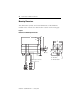
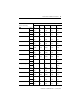
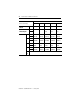
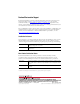
Shaft End Hole
Thread
mm — — M5 x 0.8 M5 x 0.8 M5 x 0.8
Shaft End Hole
Thread Depth
mm — — 12 12 12
(in.) — — (0.5) (0.5) (0.5)
Tolerances AH mm ±0.8 ±0.8 ±0.8 ±0.8 ±0.8
(in.) (±0.315) (±0.315) (±0.315) (±0.315) (±0.315)
AK mm -0.021 -0.021 -0.025 -0.025 -0.030
(in.) (-0.0008) (-0.0008) (-0.0009) (-0.0009) (-0.0011)
L mm ±1.0 ±1.0 ±1.0 ±1.0 ±1.0
(in.) (±0.4) (±0.4) (±0.4) (±0.4) (±0.4)
U mm -0.009 -0.009 -0.011 -0.011 -0.011
(in.) (-0.0003) (-0.0003) (-0.0004) (-0.0004) (-0.0004)
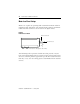
Cab
le
±100 mm (±4.0 in.)
1
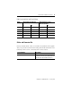
Y-Series motors are designed to metric dimensions. Inch measurements are mathematical conversions.
Dimension
1
(Refer to drawing)
Motor
Y-1002 Y-1003 Y-2006 Y-2012 Y-3023