WebPak 3000 Operator Interface Module (OIM) User Guide Instruction Manual D2-3445
The information in this manual is subject to change without notice. Throughout this manual, the following notes are used to alert you to safety considerations: ! ATTENTION: Identifies information about practices or circumstances that can lead to personal injury or death, property damage, or economic loss. Important: Identifies information that is critical for successful application and understanding of the product.
CONTENTS Contents Chapter 1 Introduction to the WebPak 3000 OIM 1.1 Related Publications ........................................................................................ 1-1 1.2 Getting Assistance from Reliance Electric....................................................... 1-1 Chapter 2 Description of the OIM Keypad, Display, and Indicators 2.1 Keypad ............................................................................................................ 2-1 2.2 The Display................
Chapter 6 Using the OIM to Monitor and Control the Drive 6.1 Using the OIM to Monitor Drive Outputs ..........................................................6-1 6.1.1 Description of the Monitor Mode Outputs ..............................................6-1 6.1.2 Selecting the Outputs to Monitor ...........................................................6-2 6.1.3 Using Help in Monitor Mode ..................................................................6-2 6.2 Selecting the Control Source ...............
List of Figures Figure 2.1 – OIM Keypad, Display, and Indicators ................................................... 2-1 Figure 2.2 – OIM Display in Program Mode ............................................................. 2-5 Figure 3.1 – OIM Power-Up Sequence..................................................................... 3-1 Figure 3.2 – Contrast Adjustment Screen................................................................. 3-2 Figure 3.3 – Language Selection Screen ............................
IV WebPak 3000 OIM User Guide
List of Tables Table 2.1 – Programming Key Descriptions ............................................................. 2-2 Table 2.2 – Control Key Descriptions ....................................................................... 2-4 Table 2.3 – Drive Status Indicators........................................................................... 2-6 Table 2.4 – Key Indicators ........................................................................................ 2-7 Table 2.5 – Special Display Characters....
VI WebPak 3000 OIM User Guide
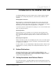
CHAPTER 1 Introduction to the WebPak 3000 OIM The WebPak 3000 Operator Interface Module (OIM) is a built-in keypad and display that allows you to change drive parameters, operate the drive, and monitor drive operation. Changing Drive Parameters Drive parameters set critical information about the drive, such as the motor rated amps and top speed.
1-2 WebPak 3000 OIM User Guide
CHAPTER 2 Description of the OIM Keypad, Display, and Indicators This chapter describes how to use the keypad, display, and indicators on the OIM to configure, monitor, and control the drive. Figure 2.1 shows the OIM in program mode with keys, indicators, and screen information identified. Figure 2.1 – OIM Keypad, Display, and Indicators 2.1 Keypad The OIM keys are grouped by programming and control functions, as shown in figure 2.1. Programming keys are described in table 2.1.
Table 2.1 – Programming Key Descriptions Key Mode Function Program or Monitor Switches between program mode and the two monitor mode screens. In fault, alarm, or diagnostics menus, returns you to the program or monitor screen you were in previously. See chapter 7 for information. Program or Monitor Program Cycles through the Fault, Alarm, and Diagnostics menus. Use these menus to review, reset, and clear faults and alarms. You can also display diagnostic information for troubleshooting the drive.
Table 2.1 – Programming Key Descriptions Key Mode Program Function In a menu, selects the option at the cursor. In a parameter entry screen, allows you to change input parameter values. If a list is available for the parameter, selects the value at the cursor. When the parameter value has been changed, saves the new value. Monitor Saves the keypad reference. See section 6.3 for information on the reference.
Table 2.2 – Control Key Descriptions Key Mode Function Program or Monitor Allows you to select from a list of possible sources for drive control signals. is not active when the drive is running or jogging, and during Quick Start and self-tuning. See section 6.2 for information on selecting a control source. Program or Monitor When is set to KEYPAD and the drive is ready, holding down jogs the motor. The motor stops when is released. When jogging, the motor ramps up to JOG SPEED (P.
2.2 The Display The OIM screens help you configure and monitor the drive. Figure 2.2 shows the OIM screen at the Main Menu in program mode. Figure 2.2 – OIM Display in Program Mode The display contains three main areas: • The drive status indicator area. See section 2.2.1 • The display area, where the program or monitor mode information is displayed. See chapter 4 for information on program mode. See chapter 6 for information on monitor mode. • The key indicator area. See section 2.2.2.
2.2.1 Drive Status Indicators The indicators on the right of the display allow you to check the status of the drive. In figure 2.2, the Interlocks OK and Drive Ready indicators are shown on. The indicators are described in table 2.3. Table 2.3 – Drive Status Indicators Indicator Fault Alarm Interlocks OK Drive Ready Running Current Limit Torque Limit 2-6 State Description On At least one fault has occurred. See chapter 7 for fault information. Off There are no faults.
2.2.2 Key Indicators There are five indicators at the bottom of the screen above the keys. When is set to KEYPAD, these indicators tell you which setting is selected by the key. If one of the other control sources is selected, these indicators tell you the setting selected by that control source. In figure 2.2, the keys are set to PROGRAM and KEYPAD. Indicators are described in table 2.4. Table 2.4 – Key Indicators Key Indicator Above Possible Indications Description PROGRAM The OIM is in program mode.
2.2.3 Special Display Characters There are several special characters you might see on the display. They are described in table 2.5. Table 2.5 – Special Display Characters Character or ] Description The cursor. Indicates the currently selected options. Use and to move the cursor. Use and to move the ] cursor. ▲ Displayed if more text or options are available above the top selection. Press ▼ to view the information. Displayed if more text or options are available below the top selection.
CHAPTER 3 Powering Up and Adjusting the OIM This chapter tells you what to expect on power up and power down and how to make adjustments for your application. 3.1 Powering Up the OIM The OIM is powered when the drive is powered. During power up, the OIM establishes communication with the drive and reads drive information from the Regulator board. The OIM indicators are off and the display goes through the power-up sequence shown in figure 3.1.
3.2 Adjusting the Screen Contrast If the display is difficult to read, you can adjust the contrast. You can do this at any time except when you are in a parameter value entry screen or during self-tuning. You might need to change the display contrast periodically because of ambient temperature changes. To adjust the screen contrast: Step 1. Press . The contrast adjustment screen is displayed, as shown in figure 3.2. Figure 3.2 – Contrast Adjustment Screen Step 2.
3.3 Changing the Language Displayed on the OIM The OIM can display text in English, German, French, Spanish, or Italian. In addition, you can select CODE, which displays the parameter code numbers instead of names, with all other text in English. (Parameter code numbers are provided in the software manual.) The default language setting is English. You can change the language at any time except when you are in a parameter value entry screen or during self-tuning. To change the language: Step 1. Press .
3.4 Scaling Values Displayed on the OIM You can scale speed and load units to match your application requirements. You can select from pre-defined units, or configure your own units through the OTHER option. (OTHER is available only for speed units.) Scaling these units affects only the OIM display.
3.4.1 Changing the Scaling of Speed and Load Units Examples in this procedure are for speed unit scaling. The same basic steps are used to configure load units. To scale units: Step 1. Press until the key indicator reads PROGRAM. Press until “WebPak 3000 Main Menu” is displayed at the top of the screen. Step 2. Press to point the cursor ( ) to Operator Interface. Press Step 3. Press to point the cursor to Define User Units. Press the menu shown in figure 3.4. .
3.4.2 Scaling Speed Units to Custom Settings Complete the procedure in “Changing the Scaling of Speed and Load Units” on page 3-5 before proceeding. If you selected OTHER for the speed units, screens are displayed that allow you to customize your scaling units. The first screen for the speed units is shown in figure 3.6. Figure 3.
Step 3. Determine the full scale value for your display units. This is the value that will be displayed for the maximum value of the units. For example, if GEAR IN SPEED (P.011) is set at 1750 RPM and you want to display 100 inches/second when the speed is at 1750 RPM, you will enter a full scale value of 100. The full scale value can be from 1 to 10,000. Step 4. To configure the full scale value, press or ] to move the cursor ( ) to the number or the sign that needs to change. Press the number or sign.
3-8 WebPak 3000 OIM User Guide
CHAPTER 4 Basics of Configuring the Drive Using the OIM Configuring the drive customizes it for your application. You can use the OIM, WebPak CS software, or network to configure the drive.
4.2 Accessing OIM Menus and Parameters OIM menus and parameters are accessed in program mode. To select program mode, press until the key indicator reads PROGRAM. If you exit from a menu or parameter list using , you return to monitor mode. When you return to program mode, the last menu or parameter that was displayed is displayed again. To go to the Main Menu, press until “WebPak 3000 Main Menu” is displayed at the top of the screen. 4.2.
4.2.2 Using Help in Program Mode In program mode, you can access help for menus and parameter entry screens. To get help, press when the menu or parameter entry screen is displayed. When you have read the help screen, press to return to the previous screen. If you see ▲ or ▼ on the help screen, there is more text. Press the additional text. or to display The Main Menu help screen is shown in figure 4.2.
4.2.3 Accessing the Parameters Parameters are accessed through the menus. The menu paths to get to parameters are provided: • In appendix A of this manual. • As part of the parameter descriptions in the software manual. Some parameters and parameter options are only available if the appropriate option is installed. For example, ENCODER PPR (P.107) is only displayed if a Pulse Encoder kit is installed. The cursor changes to a lock ( ) for parameters or options that are not available.
Step 3. Make sure the cursor is pointing at Analog I/O. Press menu is displayed, as shown in figure 4.7. $QDORJ , 2 , 2 (;3$16,21 .,7 7(16,21 6(737 6,* 7<3( 7(16,21 6(732,17 =(52 7(16,21 6(732,17 *$,1 . The Analog I/O ,167$//(' Figure 4.7 – Analog I/O Menu At this point, you can view or change parameter values. See the next sections. 4.2.4 Viewing Parameter Values In the parameter lists, parameter values are shown to the right of the parameter name, as shown in figure 4.7.
Important: To exit a parameter entry screen without making changes, press . To change a parameter value: Step 1. Go to the menu that contains the parameter you want to change by using the procedure in section 4.2.3, “Accessing the Parameters”. Step 2. Press to move the cursor until it points to the parameter. Press . Step 3. You will see either: • the existing value with the cursor blinking at the far right digit, like the screen shown in figure 4.8.
Step 6. Press to accept the changed value and go to step 7. Step 7. Press to return to the list of parameters. Step 8. To save the changes to the parameters, you must perform a memory save. See section 4.4, “Saving and Restoring Parameter Values”. Step 9. Record changes to parameter values in the software manual. 4.2.6 Parameter Values That Cannot Be Changed In some cases, you cannot change parameter values. If this is the case, an error message is displayed when you try to select the parameter.
The PASSWORD parameter toggles the program protection setting. If program protection is enabled, this procedure disables it. If disabled, the procedure enables it. To enable or disable software program protection: indicator reads PROGRAM and “WebPak 3000 Step 1. Press until the Main Menu” is displayed at the top of the screen. Step 2. Select the Operator Interface menu. Step 3. Select the PASSWORD parameter.
4.4 Saving and Restoring Parameter Values Through the OIM, you can save parameter values, restore parameter values from a previous save, or restore default parameter values. Memory Save You must use Memory Save to save changes to parameter values and the language setting through a power cycle. Any values that are not saved revert to the previous value on power cycle. Important: Memory Save does not save the PASSWORD parameter setting. To save the PASSWORD, you must use the WebPak CS software.
Step 4. Select the action you want to perform. Press . Depending on the action you select, you will see: • Memory Save:“The current parameter values will be saved to memory. Continue?” • Memory Restore: “The last saved values will be restored. Continue?” • Restore Defaults: “The factory default values will be restored. Continue?” An example of the Memory Save message is shown in figure 4.12. Figure 4.12 – Memory Save Screen Step 5. To select YES, press . Step 6. Press .
CHAPTER 5 Using Quick Start Quick Start lets you configure the most commonly used parameters through one menu. This helps you set up the drive as quickly as possible. Brief descriptions of Quick Start parameters are provided in section 5.5 in the order they are displayed as you go through Quick Start. For full parameter descriptions, see the software manual. Record your parameter configuration in the software manual. 5.
The exit options are: • Return to previous step: Returns to the previous parameter. After you accept that parameter value, Quick Start resumes from that parameter. To go back several parameters, you can press times as needed. and select “Return to previous step” as many • Exit Quick Start using changes: Exits Quick Start and accepts any changes. You must use Memory Save to save the changes through a power cycle. See section 4.4, “Saving and Restoring Parameter Values”, for more information. • Exit Q.S.
4XLFN 6WDUW *($5 ,1 63((' 27+(5 530 Figure 5.2 – First Quick Start Parameter Entry Screen Step 5. Use the procedure described in section 4.2.5 to change the value. Press . Quick Start automatically takes you to the next parameter entry screen. Step 6. Continue going through the Quick Start parameters, changing values as needed. Press to accept values and move to the next parameter. Step 7. After the final parameter entry screen (MOTOR HOT FLD AMPS (P.
5.4 Self-Tuning the Current Minor and Speed Loops ! ATTENTION: Before self-tuning, verify that no overhauling or hanging loads are on the motor. Self-tuning will not operate properly if these types of loads exist. Failure to observe this precaution could result in bodily injury. ATTENTION: The motor will rotate during self-tuning. Stay clear of rotating machinery. Failure to observe this precaution could result in bodily injury.
Step 4. Set to KEYPAD or TERMBLK. See section 6.2 for instructions. Step 5. Clear any faults from the fault log. See chapter 7 for information. If you do not do these steps, you will get an error message when you try to start self-tuning. 5.4.2 Performing the Self-Tuning Procedure Before self-tuning, complete the steps in section 5.4.1. To perform self-tuning: Step 1. Configure the self-tune parameters listed here. For descriptions of these parameters, see section 5.4.5, or see the software manual.
Figure 5.4 – Self-Tuning Screen Step 5. The message “Self Tuning is active” blinks on the screen during self-tuning. The current minor loop takes a few seconds to self-tune. The speed loop takes about two minutes. During self-tuning, you can go to monitor mode without disrupting self-tuning. Important: If you go into monitor mode during self-tuning, you must return to program mode at completion of self-tuning to see the following screen. Self-tuning is complete when the drive stops running.
5.4.3 Exiting Before Self-Tuning is Complete If you have not yet pressed to start self-tuning, you can stop self-tuning (and Quick Start) by pressing . The Main Menu is displayed if you enabled self-tuning in Quick Start, or the Self Tune Parameters menu. If you have already pressed to start self-tuning, press or assert the stop input to stop self-tuning. This causes a self-tuning drive fault. See the next section for information on these faults. 5.4.
5.5 Quick Start Parameter Descriptions Brief descriptions of the Quick Start parameters are provided here for your reference. Full descriptions of the parameters are provided in the software manual. These descriptions are listed in the order in which they are displayed during the Quick Start procedure. ! BASE SPEED (P.017) Specifies the speed at which the motor rotates at full application field strength and rated armature voltage.
TOP LINE SPEED Specifies the maximum line speed in feet per minute. (P.020) Parameter Range: 0 to 5000 FPM Default Setting: 500 FPM Parameter Type: Configurable ATTENTION: Do not allow the motor to exceed the maximum safe speed of the motor or driven equipment as determined by the equipment manufacturer. Failure to observe this precaution could result in bodily injury. ! MOTOR RATED ARM AMPS Identifies the rated armature current as is appears on the motor nameplate. (P.
REVERSE DISABLE (P.015) Enables or disables the speed reference from dropping below zero. Parameter Range: OFF ON Default Setting: OFF Parameter Type: Configurable ON: The speed reference is prevented from dropping below zero. OFF: The speed reference can drop below zero and the drive can operate in the opposite direction. FEEDBACK SELECT Selects the type of feedback signal used for the speed/voltage loop. (P.
ANLG TACH VOLTS/1000 Specifies the scaling of the analog tachometer (as it appears on the tachometer nameplate) in volts per 1000 RPM. (P.203) Parameter Range:* 18.0 to 200.0 VOLTS/1000 RPM Default Setting: 18.0 VOLTS/1000 RPM Parameter Type: Configurable *Depending on the setting of GEAR IN SPEED (P.011), the high limit might be less than 200.0 to prevent the tachometer voltage from exceeding 250V. This parameter is only available if FEEDBACK SELECT (P.200) is set to DC TACH.
DECELERATION TIME Sets the minimum time in which the selected speed reference can change from GEAR IN SPEED (P.011) to zero. (P.002) Parameter Range: 0.1 to 300.0 SECONDS Default Setting: 5.0 SECONDS Parameter Type: Tunable If TRIM MODE SELECT (P.110) is set to PROPORTIONAL, the actual time to decelerate might be modified by DRAW PERCENTAGE OUT (P.196). MINIMUM SPEED Selects the minimum speed of the drive when running. It is typically greater than zero. (P.
MAXIMUM SPEED The maximum speed of the drive that can be supported by the application or process. (P.004) Parameter Range: 1 to GEAR IN SPEED (P.011) (RPM or user-defined units) Default Setting: 500 RPM Parameter Type: Tunable If raising this value causes MINIMUM SPEED (P.003) to become less than 10% of an alarm is generated. MAXIMUM SPEED, This is typically set to base speed from the motor nameplate.
POSITIVE CURRENT LIM Sets the highest amount of current (% full load amps) for the forward bridge. (P.005) Parameter Range: 0 to MAXIMUM CURRENT (%FLA) Default Setting: 150 %FLA Parameter Type: Tunable This parameter is used as a high limit for the speed loop PI block when POS (P.223) is set to REGISTER. CURRENT LIM SEL NEGATIVE CURRENT LIM Selects the highest amount of current (% full load amps) for the reverse bridge. (P.006) Parameter Range: When NEG CUR LIM INV EN (P.
MOTOR HOT FLD AMPS Sets the motor nameplate value of the rated hot field amps. This input is the basis of field current scaling. (P.510) Parameter Range: 0.11 to INSTALLED SUPPLY RATING (4.00, 10.00, or 20.00 AMPS) Default Setting: 0.01 AMPS Parameter Type: Configurable If the factory defaults are restored, or if a valid value has not yet been entered for this parameter, the DC field voltage is fixed at 150V on a 230VAC line, or at 300V on a 460VAC line.
5-16 WebPak 3000 OIM User Guide
CHAPTER 6 Using the OIM to Monitor and Control the Drive The OIM allows you to monitor the speed, armature voltage, load, and current keypad reference outputs to the motor. You can choose between two viewing options. The OIM also allows you to control the drive. Motor control options available through the OIM include starting, stopping, jogging, and setting the manual reference and control source. 6.
6.1.2 Selecting the Outputs to Monitor You can view one of two monitor mode screens. The first monitor mode screen shows all four monitored outputs. The second monitor mode screen shows the motor speed and motor load without labels, but in larger text so the values can be read from a distance. You can switch between the monitor mode screens at any time. To select monitor mode: until the key indicator switches from PROGRAM to MONITOR. The Step 1.
6.2.1 About the Control Source The possible control sources are: • KEYPAD: • TERMBLK: Control is through Regulator board terminals 16 through 20. See the hardware manual for terminal descriptions and wiring instructions. • SERIAL: • NETWORK: Control is through the keypad. Control is through a personal computer running the WebPak CS software. Control is through a network such as the AutoMax Network Communication kit.
6.2.2 Setting the Control Source To select the control source: Step 1. Stop the drive if it is running. Step 2. Press . The screen shown in figure 6.3 is displayed. Figure 6.3 – CONTROL SOURCE SELECT Screen Step 3. Press or to move the cursor to the control source you want. Step 4. Press to accept the option and return to the previous screen. The option you accepted is displayed in the key indicator. 6.
To Jog the Drive: Press to jog the motor. The drive ramps up to the reference in the time set by JOG ACCEL/DECEL TIME (P.013). The motor runs as long as is held down. When is released, the motor ramps to stop in the time set by JOG (P.013). ACCEL/DECEL TIME 6.3.2 Stopping the Drive When the drive is running, pressing STOP MODE SELECT. stops the drive in the manner selected by When the OIM is connected and communicating with the drive, is always active, regardless of the setting of ! .
6-6 WebPak 3000 OIM User Guide
CHAPTER 7 Troubleshooting the Drive Using the OIM Using the OIM, you can troubleshoot drive problems using one of these methods: • If a fault or alarm message is displayed, you can use the message and the Fault or Alarm Menu to identify the problem. • If the drive is not ready or has stopped, you can use the Diagnostics Menu to identify the problem. • If a program error message is displayed, you can use the message to identify the problem. ! 7.
Figure 7.2 – Example of an Alarm Screen Press to clear the fault or alarm message. If multiple faults or alarms occurred, they are displayed after you press . If the fault or alarm log is full, a message is displayed. To log future faults and alarms, you must clear the log (section 7.2.2). Each log holds up to ten entries. To identify the problem when a fault or alarm occurs, use the Fault or Alarm Menu or the tables in the hardware manual.
7.2.1 Reviewing the Fault and Alarm Logs You can review the fault and alarm logs to help identify the problem and determine when it occurred. Step 1. Select Review Log from the Fault or Alarm Menu. The screen shown in figure 7.5 is displayed. If the log is empty, “Log is Empty” is displayed. Figure 7.5 – Example of a Fault Log Screen The first line in the Review Log is the most recent fault or alarm. If a fault or alarm is detected while you are in the log, the display is updated to show the new entry.
These screens show: • The fault or alarm number (on the first line). You can use this number to look up information about the fault or alarm in the hardware manual. • A one-line description of the fault or alarm. • The date and time when the fault or alarm occurred. This time is based on an internal 248-day counter. The counter is restarted when drive power is cycled, or when the clock is reset (see section 7.7, “Resetting the Clock”).
To reset the faults or alarms and clear the log Important: You cannot clear individual faults or alarms. This procedure clears the entire log. Step 1. Depending on whether you are clearing faults or alarms, do one of the following: • From the Fault Menu: Select “Clear Fault Log and Reset Faults.” • From the Alarm Menu: Select “Clear Alarm Log and Reset Alarms.” . A message is displayed that states that the alarms or faults Step 2. Press were reset and the log was cleared.
Table 7.1 – Possible OIM Responses to “Why is the Drive Not Ready?” Display Description DOWNLOAD IN PROGRESS WebPak CS configuration file download procedure is in progress or the configuration parameters are being processed. COAST/DB STOP OPEN The coast/DB stop input (TS 8) is open. CUSTOMER INTERLOCK OPEN The customer interlock (TS 9) is open. MEMORY OPERATION IS PROGRESS Non-volatile memory is being restored. DRIVE IS IN PROCESS OF STOPPING The drive is in the process of stopping.
7.4 Clearing a Programming Error Message Programming errors occur if you select an option that is not valid, such as attempting to set a read-only parameter. These errors do not affect drive operation and are not logged. To remove a programming error message, press . 7.5 Determining Why the OIM is Not Communicating with the Drive The OIM can stop communicating with the drive if the communication link is faulty, if a fatal OIM error occurs, or if a fatal regulator error occurs.
7.6 Replacing the OIM ! ATTENTION: Only qualified electrical personnel familiar with the construction and operation of this equipment and the hazards involved should install, adjust, operate, or service this equipment. Read and understand this section in its entirety before proceeding. Failure to observe this precaution could result in severe bodily injury or loss of life. ATTENTION: Do not install or remove the OIM with power applied to the drive.
You must remove the OIM assembly from the drive to replace the circuit board. See section 7.6.1, “Preparing to Replace the OIM”, and section 7.6.2, “Accessing the OIM and Disconnecting It from the Regulator Board”, for instructions. To replace the circuit board: Step 1. Place the OIM assembly face down on a surface that will not scratch the OIM front panel. Step 2. Remove the four screws holding the circuit board to the mounting plate. Step 3. Lift the circuit board from the standoffs.
The clock is primarily used to show when a fault or alarm occurred. It is reset by cycling power or by using the procedure described here. To reset the clock: until the key indicator reads PROGRAM. Step 1. Press Step 2. Press or Press . Step 3. Press or until the cursor ( ) is pointing to Operator Interface. until the cursor is pointing to Reset Clock. Press . Step 4. The OIM resets the elapsed time clock to 000 days 00 hours 00 mins 00 secs and displays the message shown in figure 7.9.
APPENDIX A OIM Menu Structure This appendix shows the OIM menu structure and the parameters in the menus. In these lists, parameter names are shown in upper case and menus are shown in lower case. A.1 WebPak 3000 Main Menu To access the Main Menu, press until WebPak 3000 Main Menu is displayed at the top of the screen.
FEEDBACK SELECT (P.200) ANLG TACH VOLTS/1000 ENCODER PPR (P.203) (P.207) ACCELERATION TIME (P.001) DECELERATION TIME (P.002) MINIMUM SPEED MAXIMUM SPEED (P.003) (P.004) JOG ACCEL/DECEL TIME JOG SPEED (P.013) (P.012) POSITIVE CURRENT LIM (P.005) NEGATIVE CURRENT LIM IR COMPENSATION (P.006) (P.206) MOTOR HOT FLD AMPS (P.510) J11 ANLG TACH VLT SCL (P.792) J14 ANLG TACH VLT RNG J18 ARM I FB RESISTOR (P.793) (P.395) Self Tune Drive Reference Drive Reference Test Points LINE SPEED (P.
Drive Reference Trim (P.107) TRIM REF REGISTER (P.108) TRIM REFERENCE SELECT TRIM RANGE (P.109) TRIM MODE SELECT (P.110) Drive Reference Limits GEAR IN SPEED (P.011) (P.004) MAXIMUM SPEED MINIMUM SPEED (P.003) REVERSE DISABLE (P.015) MINIMUM SPEED BYPASS BASE SPEED (P.111) (P.017) (P.122) STOP DECEL SELECT (P.018) RAMP STOP DECEL TIME Drive Reference Ramp ACCELERATION TIME (P.001) DECELERATION TIME (P.002) S-CURVE ROUNDING (P.014) JOG ACCEL/DECEL TIME SPEED RAMP BYPASS (P.013) (P.
DIAMETER/TAPER ZERO DIAMETER/TAPER GAIN DIAMETER/TAPER IN (P.105) (P.104) (P.192) (P.198) SPEED RAMP INPUT TP Speed/Voltage Loop (SPD) Speed/Voltage Loop (SPD) Test Points (P.295) SPD LOOP REFERENCE (P.296) SPD LOOP FEEDBACK SPD LOOP ERROR (P.297) SPD LOOP LAG OUTPUT SPD LOOP OUTPUT (P.298) (P.299) CURRENT COMPOUND TP ARMATURE VOLTAGE (P.289) IR COMPENSATION TP (P.290) ANALOG TACH FEEDBACK ENCODER FEEDBACK (P.293) (P.291) (P.
SYSTEM INERTIA (P.222) Speed/Voltage Loop (SPD) Feedback (P.200) FEEDBACK SELECT MOTOR RATED ARM VOLTS (P.009) (P.205) ARM VOLTAGE ZERO ADJ (P.204) ARM VOLTAGE GAIN ADJ (P.289) ARMATURE VOLTAGE (P.202) ANALOG TACH ZERO ADJ ANALOG TACH GAIN ADJ (P.201) ANALOG TACH FEEDBACK (P.291) ANLG TACH VOLTS/1000 (P.203) J11 ANLG TACH VLT SCL (P.792) J14 ANLG TACH VLT RNG ENCODER PPR (P.793) (P.207) Current Minor Loop (CML) CML Test Points CML REFERENCE CML FEEDBACK CML ERROR (P.396) (P.
SELF TUNE BRIDGE (P.220) SELF TUNE STABILITY (P.219) Self Tuning POS CURRENT LIM SEL (P.223) NEG CURRENT LIM SEL (P.224) CML Feedback Scaling (P.007) MAXIMUM CURRENT MOTOR RATED ARM AMPS CML FEEDBACK GAIN ADJ J18 ARM I FB RESISTOR CT TURNS RATIO (P.008) (P.300) (P.395) (P.010) Three Phase AC Line NOMINAL AC LINE FREQ (P.306) NOMINAL AC LINE VOLTS AC LINE PERIOD (P.307) (P.393) AC LINE VOLTAGE (P.392) PLL MAXIMUM ERROR (P.308) SCR Diagnostics OPEN SCR SENSITIVITY (P.
Input/Output Analog I/O I/O EXPANSION KIT (P.797) TENSION SETPT SIG TYPE (P.413) TENSION SETPOINT ZERO (P.414) TENSION SETPOINT GAIN TENSION SETPOINT IN (P.415) (P.492) TENSION/DANCER ZERO (P.416) TENSION/DANCER GAIN (P.417) TENSION/DANCER FDBK (P.493) ANLG OUT 1 SELECT (P.404) ANLG OUT 1 ZERO ADJ (P.402) ANLG OUT 1 GAIN ADJ (P.400) ANLG OUT 2 SELECT (P.405) ANLG OUT 2 ZERO ADJ (P.403) ANLG OUT 2 GAIN ADJ (P.401) ANLG OUT 3 SELECT (P.418) ANLG OUT 3 SIG TYPE (P.
(P.317) SLACK TAKE UP COMMAND CURRENT MEM COMMAND TENSION COMMAND (P.319) (P.850) Frequency I/O I/O EXPANSION KIT FREQ IN ZERO (P.797) (P.423) FREQ IN FULL SCALE FREQ IN (P.424) (P.491) FREQ OUT SELECT FREQ OUT ZERO (P.425) (P.426) FREQ OUT FULL SCALE (P.427) Level Detectors I/O EXPANSION KIT (P.797) LEVEL DETECT 1 A SEL (P.602) LEVEL DETECT 1 B SEL (P.610) LEVEL REGISTER 1 (P.603) LEVEL DETECT 1 DELAY (P.604) LEVEL DETECT 1 OUTPUT (P.648) LEVEL DETECT 2 A SEL (P.
NETW OUT REG 2 SELECT (P.903) NETW OUT REG 3 SELECT (P.904) NETW IN REG 1 (P.905) NETW IN REG 2 (P.906) NETW IN REG 3 (P.907) Field Current Regulator FLD CURRENT REGULATOR (P.586) Field Loop Test Points FIELD REFERENCE FIELD FEEDBACK (P.590) (P.589) (P.599) FIELD ECONOMY ACTIVE FIELD DELTA (P.588) Field Loop Tuning FIELD REF REGISTER (P.513) FIELD PI PROP GAIN (P.514) FIELD PI LEAD FREQ (P.515) FLD WEAKEN THRESHOLD IR COMPENSATION (P.518) (P.206) FLD WEAKEN PROP GAIN (P.
Drive Information Correct Scaling Jumper Positions J11 ANLG TACH VLT SCL (P.792) J14 ANLG TACH VLT RNG J18 ARM I FB RESISTOR ENCODER KIT (P.798) NETWORK KIT (P.796) I/O EXPANSION KIT (P.395) (P.797) FLD CURRENT REGULATOR POWER UNIT TYPE (P.793) (P.586) (P.795) J15 REGULATOR TYPE (P.799) REGULATOR SW VERSION (P.
P.132 DIAMETER CALC OUTPUT P.133 SPEED CROSS OVER P.134 STALL TENSION FIX P.135 STALL TENSION PERCENT P.136 LINE SPEED HYSTERESIS P.226 NEG CUR LIM INV EN P.227 TACH LEAD FLT THRESH P.228 TACH LEAD FLT DELAY P.229 INERTIA GAIN DECEL P.230 INSTANTANEOUS INERTIA P.231 POS LEADLAG LOW FREQ P.232 POS LEADLAG RATIO P.233 POS RAMP TIME P.234 POS PI LEAD FREQ P.235 POS PI LIMIT P.236 POS PI PROP GAIN P.237 POS RAMP OUTPUT P.239 POSITION CROSS OVER P.240 POSITION REFERENCE P.241 POSITION VERNIER P.
P.253 POS PROFILER ENABLE P.254 POS LOOP ERROR P.255 POS LEADLAG BYPASS P.312 INV FAULT AVOID SEL P.313 CURRENT MEMORY BOOST P.314 CURRENT MEMORY ENABLE P.315 LOSSES COMP SELECT P.316 LOSSES COMPENSATION P.318 SLACK TENSION PI LIM P.390 CML RAMP INPUT TP P.391 CML SPEED REFERENCE P.406 ANLG OUT 1 FILTER EN P.407 ANLG OUT 2 FILTER EN P.489 TEN/DANCER FDBK SCALED P.490 UNDERWIND DIN TP P.494 SLACK TAKE UP DIN TP P.497 DIAMETER RESET TP P.522 FIELD CURRENT 1 P.523 FIELD CURRENT 2 P.524 FIELD CURRENT 3 P.
P.536 FIELD INPUT 7 P.537 FIELD INPUT 8 P.538 FIELD SHAPING LAG P.539 FIELD SHAPING TYPE P.540 MOTOR SPD AT MAX FLD P.608 TACH LOSS SCR ANGLE P.609 PHASE LOSS DETECT EN P.610 LEVEL DETECT 1B SEL P.611 LEVEL DETECT 2B SEL P.810 OCL PARALLEL OFFSET P.811 CURRENT/SPEED SWITCH P.812 OCL PROP TRIM GAIN P.814 OCL TYPE 3 POSN REG EN P.819 DANCER DECEL TIME P.820 DANCER LOADING P.821 DIAMETER ANALOG P.822 WINDER CORE DIA 1 P.823 DIAMETER ACCEL RATE P.824 WINDER CORE DIA 2 P.825 WINDER CORE DIA 3 P.
P.837 TEN LEADLAG SELECT P.838 TEN OUT LL LOW FREQ P.839 TEN OUT LL RATIO P.840 TEN PI LEAD FREQ P.841 TEN PI PROP GAIN P.842 TEN RAMP OUTPUT P.844 TENSION DEMAND P.845 TEN FDBK LL BYPASS P.851 TENSION FDBK MAX P.852 TENSION FDBK MIN P.853 TENSION PI LIMIT P.854 TENSION SETPOINT P.855 TENSION SETPOINT SEL P.856 TENSION VERNIER P.857 STORAGE P.858 TAPER ENABLE P.859 TAPER PERCENT P.860 TAPER REGISTER P.861 TAPER SET REGISTER P.862 TAPER SET SELECT P.863 TAPER TYPE P.864 REF RATE LAG FREQ P.
P.877 UNDERWIND COMMAND P.878 TEN PROFILER ENABLE P.879 TEN PI KP OUT P.899 STALL TENSION COMMAND P.
A-16 WebPak 3000 OIM User Guide
INDEX A alarm, 5-2 alarm, 5-2 ACCELERATION TIME (P.001), 5-11 alarms identifying, 7-1 resetting and clearing logs, 7-4 reviewing and resetting, 7-2 reviewing logs, 7-3 ANLG TACH VOLTS/1000 (P.
J motor data, 5-1 MOTOR HOT FLD AMPS JOG ACCEL/DECEL TIME (P.013), 5-13 MOTOR LOAD, (P.510), 5-15 6-1 (P.008), 5-9 (P.009), 5-9 JOG key, 2-4, 6-5 (P.012), 5-13 jogging drive, 6-4 MOTOR RATED ARM AMPS JOG SPEED MOTOR RATED ARM VOLTS K N MOTOR SPEED, key 6-1 (P.006), 5-14 control source, 6-3 non-retentive (parameter type), 4-1 NORMALIZED INDUCTANCE, 5-6 NORMALIZED INERTIA (P.
programming keys, 2-2 programming see also configuration pushbutton, coast/stop, 2-4 stopping drive, 6-5 system, 5-4 SYSTEM INERTIA (P.222), 5-4 Q T Quick Start, 5-1 exiting, 5-1 parameter descriptions, 5-8 technical assistance, 1-1 TERMBLK control source, 6-3 time, resetting, 7-9 TOP LINE SPEED (P.
Index Index-4
U.S. Drives Technical Support Tel: (1) 262.512.8176, Fax: (1) 262.512.2222, Email: support@drives.ra.rockwell.com, Online: www.ab.com/support/abdrives Publication D2-3445– March 2000 Copyright © 2000 Rockwell Automation, Inc. All Rights Reserved.