
Hardware Reference, Installation and Troubleshooting Owner manual

CE-Conformity
B-3
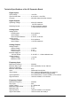
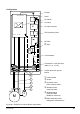
Configuration
1U, 1V, 1W
M
PE
PE
2
1
6
3
4
5
G
1C, 1D 3C, 3D
-
K1
Cabinet
Panel
AC-reactor
Converter
AC-Input contactor
SCR-protecting fuses
RFI Filter
or
HF Filter
Circuit breaker
Terminals for 4-wire AC-Input
cable (L1, L2, L3, PE)
Cabinet protection ground
busbar
➀
Cable bracket
➁
Screen
➂
Screened 3-wire
motor armature cable
➃
Shielded 2-wire
motor field cable
➄
Shielded signal
conductor cable
(feedback, reference)
➅
EMC-tested armoured
cable gland at terminal box
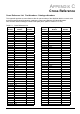
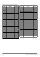
Figure B.1: Example for control cabinet configuration