
Hardware Reference, Installation and Troubleshooting Owner manual

Drive Setup and Adjustment
3-7
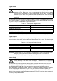
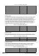
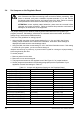
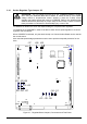
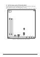
3.5 Set the Jumpers on the I/O Expansion Board
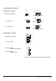
The jumper settings for the I/O Extension Board determine the Analog Input 1 and Analog
Output 1 settings as shown in the following figures 3.3 and 3.4.
The procedure is the same as for the Regulator board, described in Section 3.4 on page 3-2.
J15
J14
J12
J11
38 39 40 41 42 43 44 50 51 52
33
34
53 54 55 56 57 58 59 60 61 62 63 64 65 66 67 68 69
J10
J5 J6 J7
J8
J9
Figure 3.3 - I/O Board Layout with Jumper Locations