
Hardware Reference, Installation and Troubleshooting Owner manual
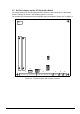

Install and Wire the Drive
2-19
Digital Inputs
ATTENTION: The user must read and understand the drive sequencing description
and state diagram (WebPak 3000 Software Reference, chapter 3) before using the
TENSION ON
input. Setting
OCL SELECT
≠
NONE
permits the
TENSION ON
input to start
the drive. Once the
TENSION ON
input is permitted to start the drive, negating the
TENSION ON
input while in any other state than the stall tension state will not stop
the drive. Failure to observe this precaution could result in severe bodily injury or
loss of life.
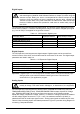
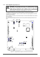
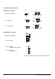
The I/O Expansion board supports five digital inputs. The function of each digital input is fixed,
and is shown in table 2.3. The drive will recognize a change in the state of a digital input signal
(e.g. 0 to 24 VDC) if it is applied for longer than 20 msec.
Table 2.3 - I/O Expansion Digital Inputs
Parameter Name Parameter Number Terminal Strip Location*
DIAMETER SELECT A TP
P.495 59
DIAMETER SELECT B TP
P.496 60
DIAMETER RST DIN TP
P.497 62
TENSION ON DIN TP
P.498 63
CURRENT MEMORY DIN TP P.499 64
* Terminals 58 and 61 (+24 VDC) and 65 (24 V COM) are available for use with the digital inputs.
Digital Outputs
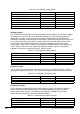
The I/O Expansion board supports two digital outputs. Digital outputs can be sourced from
various functions of the drive, and hold their state for a minimum of 20 msec. The digital output
parameters are listed in table 2.4.
Table 2.4 - I/O Expansion Digital Outputs
Parameter Name Parameter Number Terminal Strip Location
DIG OUT 1 SELECT P.409 66, 67
DIG OUT 2 SELECT P.411 68, 69
DIG OUT 1 CONTACT TYP P.410
DIG OUT 2 CONTACT TYP P.412
Important: If digital output 1 or 2 is configured as normally closed, it will act as normally open
during a power cycle until the software contact type is read. This should be
accounted for in your application program.
Analog Inputs
ATTENTION: At very low input levels, noise or drift could cause analog input
polarity to change. This could result in damage to, or destruction of, the equipment.
The I/O Expansion board supports two analog inputs: TENSION SETPOINT IN (P.492) and
TENSION/DANCER FDBK (P.493). TENSION/DANCER FDBK accepts a bipolar DC voltage
only. TENSION SETPOINT IN can be configured to accept any of the following signals:
bipolar DC voltage, unipolar DC voltage, 4-20 mA, or 10-50 mA. Analog inputs can be scaled to
use DC voltage signals as low as 4.5 V (5V + 10%), but maximum resolution (0.024%) is
obtained when the full scale input signal is used. Analog input signals are read every 20 msec.
Table 2.5 lists the analog inputs and related parameters. Figure 2.9 provides wiring diagram for
connecting 5 kΩ potentiometers.