WebPak 3000 DC Drives Hardware Reference, Installation, and Troubleshooting Instruction Manual C UL Manual P/N: R UL R 899.07.
.
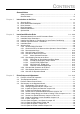
CONTENTS General Notes Safety Instructions................................................................................................ V General Notes ..................................................................................................... VI Chapter 1 Introduction to the Drive 1.1 1.2 1.3 1.4 1.5 1.6 Chapter 2 Chapter 3 2-1...2-20 Recommended AC Line and DC Armature Fuses ............................................. 2-1 Install the Drive, Dimensions .................................
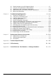
3.5 3.6 3.7 3.8 3.9 Chapter 4 Troubleshooting/Diagnostics 4.1 4.2 4.3 4.4 4.5 4.6 4.7 4.8 4.9 4.10 4.11 4.12 4.13 4.14 4.15 Chapter 5 Set the Jumpers on the I/O Expansion Board ....................................................3-7 Verify the Correct Direction of Motor Rotation .................................................... 3-9 Determine the DC Tachometer Lead Polarity..................................................... 3-9 Make Tachometer and Armature Feedback Adjustments.......................
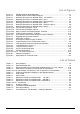
List of Figures Figure 1.1 - Sample WebPak 3000 Nameplate .........................................................................1.1 Figure 1.2 - WebPak 3000 Functional Block Diagram............................................................. 1-3 Figure 2.1 - Mounting Dimensions for WebPak 3000, 25 and 60 A...................................... 2-2 Figure 2.2 - Mounting Dimensions for WebPak 3000, 150 A.................................................. 2-3 Figure 2.
. IV WebPak 3000 DC Drive Hardware Reference
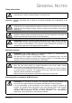
GENERAL NOTES Safety Instructions ATTENTION: Identifies information about practices or circumstances that can lead to personal injury or death, property damage, or economic loss. Important: Identifies information that is critical for successful application and understanding of the product. ATTENTION: Before installing and/or operating this device, this manual must be understood by the qualified electrical maintenance person who is familiar with this type of equipment and the hazards involved.
General Notes Copyright © 2001 Rockwell International Corporation Each reproduction of this manual may be prosecuted. The copyright of the user's manual remains at Rockwell Automation AG, CH-6036 Dierikon. Trade mark WebPak and Reliance® are registered trade marks of Rockwell Automation Manual Scope This manual contains information on drive installation, drive startup, and troubleshooting procedures.
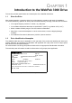
CHAPTER 1 Introduction to the WebPak 3000 Drive This section provides specifications and a description of the WebPak 3000 Drive. 1.1 Store the Drive After receipt inspection, repack the drive in its original shipping container until ready for installation. To ensure satisfactory operation at startup and to maintain warranty coverage, store the drive as follows: • In its original shipping container in a clean, dry, safe place.
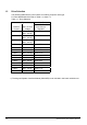
1.3 Drive Selection The following table lists the part numbers for ordering a specific drive type. For Drive Modification Kits refer to Table 1.2, sheet 1-4. Table 1.1 - Drive Selection Unit Type Nominal Current Power Unit (Basic) 1) S-6R with Max. AC-Line Field Current Voltage Regulator 25 A 500 V, 50 Hz 460 V, 60 Hz 849.01.73 60 A 500 V, 50 Hz 460 V, 60 Hz 849.03.73 150 A 500 V, 50 Hz 460 V, 60 Hz 849.05.73 250 A 500 V 849.07.73 450 A 500 V 849.09.73 800 A 500 V 849.11.
1.4 Drive Description The drive is a full-wave power converter without back rectifier, complete with a digital current minor loop and a digital major loop for armature voltage or speed regulation by tachometer or encoder feedback. The drive provides functions specifically for web-handling applications. Figure 1-2 shows a block diagram of the drive.
1.6 Optional Kits Rockwell Automation offers modification kits that broaden the application range of the drive. A summary of these kits is presented in Table 1.2. For US Model-No's refer to Appendix C. Table 1.2 - Drive Modification Kits Name Pulse Encoder Feedback Kit (incl. cable) Description Allows for digital pulse Encoder speed feedback. Part Number Catalog-No. 762.70.00 PTK Instruct. Manual Manual No. Publication No.
CHAPTER 2 Install and Wire the Drive ATTENTION: .The user is responsible for conforming to all other applicable standards. Wiring practices, grounding, disconnects, and overcurrent protection are of particular importance. Size and install all wiring in conformance with the applicable standards. Failure to observe this precaution could result in severe bodily injury or loss of life. ATTENTION: .This equipment must be connected to a power source for which it was designed.
269 25 25 219 7.0 14.0 Power connections Terminals for 25 A Unit 12 386 400 130 6 mm 1.4 Nm AC-Line 1U, 1V, 1W 6 mm 1.4 Nm Prot. earth PE 6 mm 1.4 Nm 2 2 Power connections Terminals for 60 A Unit 136 185 107 7 25 2 Motor 1D, 1C 219 25 2 Motor 1D, 1C 16 mm 2.5 Nm AC-Line 1U, 1V, 1W 16 mm 2.5 Nm Prot. earth PE 16 mm 2.5 Nm 2 2 MAX. 250 287 Weight: 10 kg Minimum clearances for air circulation: 100 mm 200 Figure 2.1: 2-2 Mounting Data for 25 A and 60 A Drives.
269 25 219 69.5 25 32.5 32.5 32.5 32.5 69.5 ø8.5 7.0 12 14.0 1U 1C 1V 1D 1W Power Connections on 1-Quadrant Units S-6 69.5 36 185 29 29 36 69.5 ø8.5 386 400 428 1C 1U 1V 1W 1D 130 Power Connections on 4-Quadrant Units S-6R 136 107 Power Connections 7 25 219 25 MAX. 250 Motor 1D, 1C Bus bars 2 90 mm AC-Line 1U,1V,1W Bus bars 2 60 mm Prot. Earth Terminals 35 mm Torque 2.
Power connections for 250 A Unit Motor 1D, 1C Bus bars 25 x 5, Hole 11 mm AC-Line 1U, 1V, 1W Bus bars 20 x 5, Hole 11 mm Prot. earth PE Bolt M10, Torque 15 Nm Power connections for 450 A Unit Motor 1D, 1C Bus bars 40 x 5, Hole 14 mm AC-Line 1U, 1V, 1W Bus bars 30 x 5, Hole 14 mm Prot. earth PE Bolt M10 Torque 15 Nm Weight: 40 kg Cooling air: 407 m3/h Air flow direction: from bottom to top Minimum clearances for air circulation: 100 mm Figure 2.3: Mounting Data for 250 A and 450 A Drives.
Power connections Motor 1D, 1C Bus bars 50 x 10, Hole 13.5 mm AC-Line 1U, 1V, 1W Bus bars 40 x 10, Hole 13.5 mm Protection earth PE Bolt M12 Torque 15 Nm Weight: 83 kg Cooling air: 814 m3/h Air flow direction: Minimum clearances for air circulation: from bottom to top 100 mm Figure 2.4: Mounting Data for 800 A Drives.
455 515 400 6 14 240 21 190 49 50 = 40 100 = DC OUTPUT 60 M12 317 197 975 200 52 905 M12 50 = 100 40 = 185 DC OUTPUT 138 418 130 154 26 26 = 60 89.5 60 89.5 60 160 = Power connections 200 Motor 1D, 1C bus bars 100 x 10, drilling 4 x M12 AC-Line 1U, 1V, 1W bus bars 60 x 10, drilling 2 x 13,5 mm Prot.
Power connections Motor 1D, 1C bus bars 120 x 10, drilling 4 x M12 Torque 25 Nm 200 AC-Line 1U, 1V, 1W bus bars 96 x 10, drilling 4 x 14 mm Prot. earth PE bus bar 60 x 10, drilling 2 x 14 mm, Weight: Cooling air: 196 kg 2000 m3/h Air flow direction: from bottom to top Minimum clearances for free air circulation: 100 mm Figure 2.6: Mounting Data for WebPak 2000A, 500V.
2.2 Install a Line Reactor or Transformer for Input Power Conditioning ATTENTION: Distribution system capacity above the maximum permitted system kVA, as well as limitation of commutation notches, requires always adding an impedance at line input (terminals 1U, 1V, 1W).You can use a 3-phase line reactor with 2% voltage drop minimum (refer to Table 5.6) or other means of adding similar impedance (e.g. matched isolation or auto transformer).
2.4 Install the Motor 1. Verify that the motor is the appropriate rating to use with the drive. 2. Install the DC motor in accordance with its installation instructions. 3. Make sure that coupled applications have proper shaft alignment with the driven machine or that belted applications have proper sheave/belt alignment to minimize unnecessary motor loading. 4. If the motor is accessible while it is running, install a protective guard around all exposed rotating parts. 5. Wire the motor to the drive.
2.5.2 Recommended Lugs for Grounding WebPak 3000 Drives in UL / cUL Version The following describes how to interpret Reliance USA lug model numbers used in grounding the WebPak 3000 drive. The lugs are non-insulated screw type (solderless) for use with solid and stranded wire.
L3 L2 L1 PE M 1 X3 + X3 J2 7 ~ 3 ~ 5 X2 2U 2V 2W POWER SUPPLY FPP 810.89.00 5 - 3 1 K1 3 4 1 J1 2 X5 1W 1V 1U 3W 1 J 2 F1 MOV 2-4 J7 3 T1 X6 4 5 T2 6 583 582 1 ~ ~ 1 2 3 J6 J1 4 - + X4 1 J3 3 J2 5 7 J3 810.79.40 REGULATOR J6 X1 X7 11 12 RC 8 R1 C1 Field Curr. Regulator 762.70.70 35 37 47 32 J4 45 V1 V4 V2 THY4 3V V5 THY2 J8 V3 THY5 2 V6 481G 382G THY6 47G THY3 J5 J9 POWER INTERFACE TIC 813.39.
230 115 0 460 V Figure 2.7b: Principle wiring diagram of WebPak 3000, four quadrant S-6R, 1600 A, 575 V 2-12 WebPak 3000 DC Drive Hardware Reference 2 3 1 4 MOV 2-4 583 582 ~ ~ J6 - + J3 Field Curr. Regulator 762.70.70 35 37 810.79.40 J5 J9 J5 J6 J7 J8 I/O EXPANSION 762.70.80 J9 38.................................................69 J1 J1 OIM (Option) 922.95.
2.5.3 Wire AC-Power to the Drive ATTENTION: The user is responsible for conforming to all applicable standards. Wiring, grounding, disconnects and overcurrent protection are of particular importance. Size and install all wiring in conformance with all applicable standards. Failure to observe this precaution could result in severe bodily injury or loss of life. ATTENTION: The drive requires a three-phase power source of ether 200 - 500 or 300 - 575/690 V, 50/60 Hz (see A-2).
The following three states are considered to be permutations of RUN mode: SPEED, RUN TENSION, and JOG TENSION. The drive will remain in RUN mode until the completion of a stop sequence and the main contactor is opened. The drive is considered to be in the JOG mode if the drive was started via the JOG input. Note that the drive can enter the SPEED state from the JOG state if the SECTION RUN input is asserted while in JOG mode.
2.5.5.3 COAST/STOP Digital Input The WebPak 3000 drive can be configured to provide a coast-to-rest operational stop without physical separation of the power source from the motor. A coast-to-rest stop turns off the transistor power device drivers. Opening of the digital input COAST/STOP (terminal 8) during operation causes blocking of the regulator and the drive to Coast-to-rest.
2.5.7 Wire Optional Devices to the Drive ATTENTION: Do not route signal wiring with power wiring in the same conduit. This might cause interference with drive operation. Route signal wiring and power wiring in separate conduits. Failure to observe this precaution could result in damage to, or destruction of, the equipment. ATTENTION: Connecting an external power source to any of the +24 volt connections (terminals 1, 7, 11, and 14) on the Regulator board terminal strip will damage the drive.
Start/Stop by User Contact 1 1 2 2 + 24 V Section Run 3 3 Section Off 4 5 6 Under Jog Fwd Jog Rev 24 Analog Out1 25 Analog Out Com 26 Analog Out2 Underwind Enable Over 7 K10 27 + 24 V 8 9 28 Coast/Stop Customer Interlock Running 29 10 Fault/Alarm Reset 30 Alarm 11 + 24 V 12 Slack Take-up 13 14 15 16 Analog Manual Reference 5k 18 17 19 Auto Reference 20 21 Motor Thermostat 31 32 Fault + 24 V 24 V COM + 10 V (Isolated) - COM + Diameter Taper Range or Trim Reference +/COM HI R
2.5.8 Wire the I/O Expansion Board The I/O Expansion board provides 8 inputs and 8 outputs. These inputs and outputs are described briefly in the sections that follow. Refer to the WebPak 3000 software reference manual (D2-3444) for complete parameter descriptions. Digital Inputs Digital Outputs 64 CURRENT MEMORY 66 63 TENSION ON DIG OUT 1 COM 67 62 DIAMETER RESET DIG OUT 2 68 61 +24 V 24 V DIG OUT 1 DIG OUT 2 COM ext. supply ext.
Digital Inputs ATTENTION: The user must read and understand the drive sequencing description and state diagram (WebPak 3000 Software Reference, chapter 3) before using the TENSION ON input. Setting OCL SELECT ≠ NONE permits the TENSION ON input to start the drive. Once the TENSION ON input is permitted to start the drive, negating the TENSION ON input while in any other state than the stall tension state will not stop the drive.
Table 2.5 - I/O Expansion Analog Inputs Parameter Name TENSION SETPOINT IN TENSION/DANCER FDBK TENSION SETPT SIG TYPE TENSION SETPOINT ZERO TENSION SETPOINT GAIN TENSION/DANCER ZERO TENSION/DANCER GAIN Parameter Number P.492 P.493 P.413 P.414 P.415 P.416 P.417 Terminal Strip Location 50, 51 52, 53 * Terminals 33 (+10 VDC) and 34 (GND) are available for use with up to two 5 kΩ potentiometers. Analog Outputs The I/O Expansion board supports two analog outputs.
CHAPTER 3 Drive Setup and Adjustment ATTENTION: Only qualified electrical personnel familiar with the construction and operation of this equipment and the hazards involved should install, adjust, operate and/or service this equipment. Read and understand this section in its entirety before proceeding. Failure to observe this precaution could result in bodily injury or loss of life. 3.
3.4 Set Jumpers on the Regulator Board ATTENTION: This equipment is at line voltage when AC power is connected to the drive. Disconnect and lockout incoming power to the drive before proceeding. After power is removed, verify with a voltmeter at power terminals 1U, 1V and 1W that no voltage exists before touching any internal parts of the drive. Failure to observe these precautions could result in severe bodily injury or loss of life.
3.4.1 Set the Regulator Type Jumper J15 ATTENTION: The J15 jumper must be set to the TORQUE/CURRENT position when using the WebPak 3000 drive’s feature to “switch-on-the-fly” from speed/ voltage control to torque/current control. Applying a drive as a direct current regulator has safety issues that must be considered. Refer to the WebPak 3000 Software Reference (D2-3444) for proper setup of this function. Failure to observe these precautions could result in severe bodily injury or loss of life.
3.4.2 Setting Program Protection Jumper (OIM PROGRAM) - J16 The OIM program jumper (J16) determines whether or not parameter changes can be made through the keypad (OIM). Only programming options are affected by the setting of this jumper. The OIM drive control keys (such as RUN) and JOG are not affected. To allow keypad parameter changes, place the jumper on pins 1 and 2 (ENABLE). To prevent parameter changes through the keypad, place the jumper on pins 2 and 3 (DISABLE).
The expected analog tachometer voltage range can be set to a maximum of 250 or 62 VDC. J11 selects the hardware circuitry to maximize the resolution over the entire speed range.
3.4.10 Inspect the Spare 1 Jumper (J27) J27 is not used. The position of this jumper has no effect on the drive. Do not install a jumper block on this jumper. 3.4.11 Inspect the Filter Select Jumper (J28) J28 is not used. Do not install a jumper block on this jumper.. 3.4.12 Inspect the Spare 2 Jumper (J29) J29 is not used. The position of this jumper has no effect on the drive. Do not install a jumper block on this jumper. 3.4.
3.5 Set the Jumpers on the I/O Expansion Board The jumper settings for the I/O Extension Board determine the Analog Input 1 and Analog Output 1 settings as shown in the following figures 3.3 and 3.4. The procedure is the same as for the Regulator board, described in Section 3.4 on page 3-2. 33 34 J10 J15 J11 J5 J14 J12 J6 38 39 40 41 42 43 44 50 51 52 53 54 55 56 57 58 59 60 61 62 J7 J8 J9 63 64 65 66 67 68 69 Figure 3.
Jumper Settings on I/O Board Analog Input 1 Jumpers Voltage Input (default) J11 1 2 !! V J12 10-50 (both) 1 ! ! ! 5 2 ! ! ! 6 VOLT PARK 4-20 3 ! mA 4 - 20 mA Input 1 2 3 ! ! ! V mA 10-50 (both) 1 ! ! ! 5 2 ! ! ! 6 VOLT PARK 4-20 10 - 50 mA Input 1 2 3 ! ! ! V mA 10-50 (both) 1 ! ! ! 5 2 ! ! ! 6 VOLT PARK 4-20 Analog Output 1 Jumpers J14 ! ! ! ! ! ! ! ! mA Voltage Output (default) 8 6 4 2 ! ! ! ! ! ! ! ! mA 4 - 20 mA Output 8 6 4 2 4 - 20 mA Output internal source (default) 4 - 20
3.6 Verify the Correct Direction of Motor Rotation ATTENTION: If tachometer and/or rotation is incorrect, sudden and rapid acceleration may result which can cause overspeed of the drive. Failure to observe this precaution could result in bodily injury. Power up the Drive 1. Apply AC power to the drive after you complete the Power Off Inspection, Motor Ground Check and Drive Setup procedures . 2. See the OIM instruction manual for the displays during power-up. Turn power to the drive OFF. 1.
3.8 Make Tachometer and Armature Feedback Zero Adjustments This section describes Zero adjustments to compensate for signal drift when tachometer or armature feedback is used. See the OIM instruction manual for instructions on changing these parameter values. ATTENTION: The incorrect setting of the parameters described below can cause an overspeed condition. These parameters must be set by a qualified person who understands the significance of setting them accurately.
CHAPTER 4 Troubleshooting/Diagnostics ATTENTION: Only qualified electrical personnel familiar with the construction and operation of this equipment and the hazards involved should install, adjust, operate and/or service this equipment. Read and understand this section in its entirety before proceeding. Failure to observe this precaution could result in severe bodily injury or loss of life. ATTENTION: This equipment is at line voltage when AC power is connected to the drive.
4.4 Verifying Optional Kits Verify that each optional kit has been installed correctly according the appropriate instructions. Refer to the appropriate instruction manuals. See section 1.5 and 1.6. 4.5 Checking the Regulator Led Status Two LEDs are located on the Regulator board to indicate the operating status of the Regulator board. The cover on the OIM must be removed to observe these LEDs. Check and observe these LEDs when the OIM is not communicating with the regulator.
4.6 Fault and Alarm Messages, Descriptions and Code Numbers Table 4.1 lists all possible OIM error messages generated by the drive and fault/alarm codes. The error messages appear on the OIM display when certain drive conditions exist. Table 4-1 lists fault codes and Table 4-2 lists alarm codes. Tables 4.1 and 4.2 list fault and alarm codes by number (Fxxxxx = Fault; Axxxxx = Alarm), associated message visible at the OIM display and a description along with possible causes. Table 4.
Table 4.1 - Fault Codes (Continued) CODE DISPLAY DESCRIPTION F00005 SUSTAINED OVERLOAD Inverse time overload circuit trip. Possible causes: • Incorrect armature current feedback scaling (MOTOR RATED ARM AMPS, MAXIMUM CURRENT, CT TURNS RATIO and/or J18 not set properly). • Blown field supply fuse(s). • Mechanical binding preventing the motor shaft from rotating freely. F00006 BLOWER MOTOR STARTER OPEN This fault is not applicable on European versions WebPak 3000.
Table 4.1 - Fault Codes (Continued) CODE DISPLAY DESCRIPTION F00012 ARMATURE OVER Armature voltage exceeded 130% of MOTOR RATED ARM VOLTS (P.009). Possible causes: • MOTOR RATED ARM VOLTS not set properly. • Improper voltage loop tuning. F00013 NETWORK Network Communications is missing or failed to communicate with COMMUNICATION master. (CONTROL SOURCE SELECT set to NETWORK) TIMEOUT Possible causes: • NETW CONNECT TYPE (P.910) was changed from BASIC to FULL. • NETW DROP NUMBER (P.900) was changed.
Table 4.1 - Fault Codes (Continued) CODE DISPLAY F00061 SELF TUNING FAULT F00062 SELF TUNING FAULT F00063 SELF TUNING FAULT F00064 SELF TUNING FAULT DESCRIPTION Non-zero speed feedback at self-tune start. Possible causes: • ANALOG TACH ZERO ADJ (P.202) not set properly. • Incorrect speed feedback scaling or offset. • Overhauling load causing motor shaft rotation. Calculated armature inductance is out of range. Possible causes: • Motor armature winding not connected or open circuit.
Table 4.1 - Fault Codes (Continued) CODE DISPLAY DESCRIPTION F00200 POWER FAILURE The power supply input voltage momentarily went below tolerance. Possible causes: • AC line voltage dip. • Disconnected, loosely connected, or damaged J7 ribbon cable or power supply input wiring F00700 FACTORY The stored parameter values were determined to be invalid. Factory default values have been restored.
Table 4.2 - Alarm Codes CODE DISPLAY DESCRIPTION A00002 AC LINE VOLTAGE The AC line voltage fell below 90% of NOMINAL AC LINE VOLTS (P.307). Possible causes: • Low AC line voltage. • Incorrect value entered for NOMINAL AC LINE VOLTS (P.307). • Blown AC line fuse(s). A00003 AC LINE VOLTAGE The AC line voltage rose above 115% of NOMINAL AC LINE VOLTS LOW HIGH (P.307) Possible causes: • High AC line voltage. • Incorrect value entered for NOMINAL AC LINE VOLTS (P.307).
Table 4.2 - Alarm Codes (Continued) CODE DISPLAY DESCRIPTION A00032 SUSTAINED SPEED Motor speed did not fall below STOP SPEED THRESHOLD (P.113) in the required amount of time during a stop (this time is automatically set to two times the DECELERATION RATE (P.002) time). Possible causes: • DECELERATION RATE (P.002) not set properly. • STOP SPEED THRESHOLD (P.113) not set properly. • Overhauling load maintaining motor speed higher than the STOP SPEED THRESHOLD. • Incorrect speed/voltage feedback scaling.
4.7 Adjusting the Tachometer or Encoder Loss Sensitivity Normally, tachometer or encoder loss is reported when the SCR firing angle reaches 109° when armature current is present and the speed feedback is less than 5% of GEAR IN SPEED (P.011). If you are getting nuisance trips associated with high inertia loads, you can adjust the SCR angle at which tachometer or encoder loss is reported. For a description of parameter TACH LOSS SCR ANGLE (P.608), refer to the WebPak 3000 Software Reference manual.
4.9 SCR Diagnostics and Adjusting Open SCR Sensitivity Under normal drive operation, the load carried by each SCR is relatively equal, as shown in figure 4.1. Figure 4.1: SCR Armature Current During Normal Operation If one or more SCRs fail to turn to on, a unique pattern of insufficient or missing current pulses results, as shown in figure 4.2. Open SCR diagnostics detects SCRs that are not conducting by analyzing the level of current produced by each SCR pair firing.
Figure 4.
4.10 Armature Phase Fire Test ATTENTION: Only qualified electrical personnel familiar with the construction and operation of this equipment and the hazards involved should install, adjust, operate and/or service this equipment. Read and understand this section in its entirety before proceeding. Failure to observe this precaution could result in severe bodily injury or loss of life. ATTENTION: This is an open loop test.
Note that conduction will not begin until the firing angle is sufficiently advanced (PHASE more than 60 degrees). A rate limit block limits the rate of change of firing angle advances to prevent sudden increases in current. To prevent the drive from entering continuous conduction during this test, PHASE FIRE TEST DELTA (P.309) should not exceed 89 degrees. FIRE TEST DELTA (P.309) Figure 4.3: Thyristors Fail to contact 11. Press STOP/RESET to stop the armature phase fire test. 12.
4.11 Setting Reversed Tachometer or Reversed Encoder Lead Detection The WebPak 3000 drive includes an algorithm for detecting reversed speed feedback wiring. The logic verifies that the difference between the speed reference and the speed feedback is greater than the threshold set by TACH LEAD FLT THRESH (P.227) for the amount of time set by TACH LEAD FLT DELAY (P.228).
4.13 Checking the AC Line Period and Voltage For a description of parameters AC LINE PERIOD (P.393), AC LINE VOLTAGE (P.392) and PHASE LOSS DETECTION EN (P.609), refer to the WebPak 3000 Software Reference manual. You can use these parameters to determine the AC line period, AC line voltage, and enable phase loss detection. 4.14 Checking Drive Information For a description of parameters J15 REGULATOR TYPE (P.799), POWER UNIT TYPE (P.795) and REGULATOR SW VERSION (P.
CHAPTER 5 Replacement Parts and Accessories 5.0 Replacement of components Use original spare parts only. Selection according to Tables 5.1 to 5.6. The location of the parts is shown on the layout label inside the U-frame.
Replacement of a thyristor on power unit Type 1200 - 2000 A • Write protocol about the following procedure • Open controller and protection unit by tilting forwards. Layout of thyristor assembly is visible now on side wall. • Remove bus bars on front heat sink • Unscrew the upper cooling air deflector. Unscrew the hexagon screws for the bus bar mounting. • Unscrew the lower cooling air deflector • Loosen the two screws (13 mm) on the clamp by quarter turns.
5.1 Recommended Spare Parts Table 5.1: Urgent recommended spare parts for 4-Quadrant units S-6R 25, 60 and 150 A ThyristorModule Power Unit Type 25 A Field Rectifier P.C. Boards, Module with MOV MOV-Module 849.01.03/73 2 Module 135.60.00 60 A 849.03.03/73 2 Module 135.60.02 150 A 849.05.03/73 6 Modules 135.05.52 1 Module 124.07.00 1 MOV 123.39.30 Cooling Fan 1 Regulator 810.79.70 with Firmware EPROM 1 Interface TIA 813.41.00 1 Power Supply FPP 810.89.00 1 Field Current Regul. 762.70.
Table 5.3: Urgently recommended spare parts for 4-Quadrant Units S-6R 1200-2000 A Unit Type 1200A, 50Hz 500 V 1200A, 60Hz 500 V 1600A, 50Hz 500 V 1600A, 60Hz 500 V 2000A, 50Hz 500 V 2000A, 60Hz 500 V 1600A, 50Hz 690 V 1600A, 60Hz 575 V S-6R Part No. Thyristors 12 Pieces Fan 849.13.73 122.93.02 921.91.00 849.13.43 122.93.02 921.91.11 849.15.73 122.93.02 921.91.00 849.15.43 122.93.02 921.91.11 849.19.73 122.93.02 921.91.00 849.19.43 122.93.02 921.91.11 849.17.73 122.93.04 921.91.
5.2 Accessories Semiconductor protection fuses in the AC-line input of the converter and field circuit and in the motor armature circuit are to be selected from the following tables 5.4 and 5.5. Chokes in the AC-line input of the converter and field circuit are to be selected from the table 5.6. The fuses and chokes are externally mounted and not supplied with the power module. Table 5.4: Semiconductor Protection Fuses Motor Armature (4-Qd) Fuses Rating Part No.
Fuse Holder Dimensions Part number 511.23.00 for fuses DIN 80/ Size 00 (553.2...) up to 125 A Part number 511.24.00 for fuses DIN 80/1K, 2K (553.30../31../32..
80 (110) Fuse Holder Dimensions (continued) Part number 511.26.01 for fuses DIN 80/ 3K, 660 V, 800 - 1250 A, (553.33.xx) spacing 80 mm Part number 511.26.03 for fuses DIN 80/ 3K, 800 V, 800 - 1250 A, (553.34.xx) spacing 110 mm Bus bars Fuse To guarantee free air circulation, the fuses must be mounted between the input/output bus-bars as shown, with enough space to the next fuse. 3 Cooling air per fuse: 130 m /h Fuse Nominal Part Number Current A B C D E F G H Pv 553.72.
Table 5.6: Iron Core Choke Selection The AC-line input chokes 252.40.xx produce 2% voltage drop at 400 V and rated current. The AC-line input chokes 252.44.xx produce 2% voltage drop at 690 V and rated current. Note, that for applications with radio frequency interference filters (RFI) chokes for 2% voltage drop at rated input voltage up-to 500 V and 4% voltage drop at 690 V are mandatory.
W2 W1 V 2 V 1 U 2 U 1 B A A U1 V1 W1 U2 V2 W2 B = E D F = F G E D C H G H (1) (2) ∆ Protection earth connection stud Pv [W] Fig. Used for 4.7 50 1 85 6.5 60 1 Converter Input 72 90 7.8 70 1 52 72 95 7.8 80 2 120 72 93 115 11 90 2 -- 240 75 97 170 18 130 2 260 -- 240 75 96 170 26 150 2 290 260 -- 240 100 116 190 26 170 2 290 320 320 -- 300 80 116 220 35 225 2 252.40.10 280 270 320 300 108 123 180 50 365 2 252.
EMC Filters for WebPak 3000 General Description Power converters in general cause line disturbances over a wide frequency range. Through the correct connection of the adapted filters (HF filter or Radio Frequency Interference (RFI) filter according to the following Table 5.7), the conducted emissions in the frequency range 150 kHz to 30 MHz can be kept below the limits stated in product standard EN 61800-3.
Radio Frequency Interference Filter a) WebPak 3000 converters with AC line input currents below 100 A: If the RFI filter is connected, the HF emission limits for class A, group 1 (EN 55011) according to the product standard EN 61800-3 are met and the drive is CE conform. This applies for the 1st environment (residential) as well as for the 2nd environment (industrial supply network).
Radio Interference Filters 25, 36 and 50 A, 440 V M6 150 L1 42.5 L3 L2 LINE LOAD E' L3' L2' 21 20 42.5 6.5 115 200 250 E 65 L1' 20 17 120 135 Filter Part No.: 839.72-05 839.72-06 839.72-07 Rated Current 25 A 36 A 50 A Power loss: Weight: 8W 3 kg 9W 3.1 kg 11 W 3.5 kg Figure 5.
Radio Interference Filter 80 A, 440 V 90 150 M10 LOAD L3' L2' L1' 15 E' 400 L1 350 L3 L2 LINE 375 427 E 30 30 30 6.5 70 130 Filter Part No.: 839.72-09 Power loss: Weight: 23 W 9.5 kg Figure 5.
Radio Interference Filter 100 A, 500 V 275 30 80 30 215 22 4 x M6 E L1 L2 LINE 4 x M8 L3 785 741 E' LOAD L1' L2' 50 50 741 L3' 22 62 22 50 63 22 18 47 15 M8 Filter Part No.: 839.71-53 Power loss: Weight: 75 W 9.5 kg Figure 5.
Radio Interference Filter 150 A, 460 V 194 17 160 25 55 M10 1L1 1L2 55 45 25 1L3 24 17 180 163.5 550 475 292 95 LOAD PE 1L1 1L2 1L3 7 55 Filter Part No.: Power loss: Weight: 839.70-20 12 W 14 kg Figure 5.
Radio Interference Filter 180 A, 440 V and 280 A, 500 V J E 4 M10 E A L3 L2 L1 LINE B F P LOAD L3' L2' L1' 15 E' H G 6.5 G L I Filter [A] Part No. A B G H 132 470 25 28 280 839.72-67 742 530 103 153 660 31 59 180 839.74-22 537 360 Figure 5.8: 5-16 C 88 E C F R Pv Terminal 2 [kg] [W] max.
Radio Interference Filter 270 A, 440/500 V 30 65 350 M12 L3 L2 LINE L1 5.1 LOAD L3' L2' E' L1' 65 30 110 135 550 135 110 E 160 50 335 40 80 80 80 320 Filter Part No.: 839.70-66 Power loss: Weight: 26 W 48 kg Figure 5.
Radio Interference Filter 340 A, 440/500 V 420 110 797 797 873 12 24.5 360 Filter Part No.: 839.71-68 Power loss: Weight: 50 W 22 kg Figure 5.
Radio Interference Filter 250, 500, 1000 and 1600 A, 440 V C D PE L1/L3 L2 = L3 L2 LINE L1 T R A F B G E LOAD L2' L3' PE' L1' P = L1'/L3' L2' S Q M H L K I [A] Filter Part No. 250 500 A B C D E F G H K L M 839.73-25 460 350 230 149 260 200 285 120 100 79.5 24 839.73-31 590 500 250 154 280 280 305 150 93 59.5 24 1000 839.73-35 840 650 400 204 440 320 465 262 127 79 34 1600 839.
Radio Interference Filter 600 ,1000 and 1600 A, 500/690 V C D PE L1/L3 L2 = L3 L2 LINE L1 T R A F B G E L3' LOAD L2' PE' L1' P = L1'/L3' L2' S Q M H L K I [A] Filter Part No. 600 A B C D E F G H K L M 839.73-92 590 500 250 154 280 280 305 150 94.5 61.5 26 1000 839.73-95 610 500 250 198 280 280 305 172 90 51 26 1600 839.
APPENDIX A Technical Specifications AC-Line Considerations Requirement 1) Limiting the AC line symmetrical fault current to 100 kA (max. for fuses) or values acc. table below for UL, cUL, as well as limiting commutation notches at the line input (terminals 1U, 1V, 1W). 2) Limiting the AC line symmetrical fault current (RMS) at the field rectifier input (terminals 3V, 3W) to 10 kA. Measures Always adding an impedance in the line input.
Input Voltage and Frequency Ratings: Nominal voltage for three-phase at terminals 1U, 1V, 1W and 2U, 2V, 2W On units 25, 60, 150 A...................................................... 200 - 500 VAC at 50 Hz 200 - 460 VAC at 60 Hz On units 500 V, 250, 450, 800, 1200, 1600 and 2000 A ..................... 200 - 500 VAC On units 575 V, 60 Hz, 1600 A ........................................................... 300 - 575 VAC On units 690 V, 50 Hz, 1600 A ..........................................................
Regulation (with 95% load change): Table A.2 - Tachometer Speed Regulation Speed Change with 95% Load Change Regulation Arrangement Armature Voltage Regulation with IR Comp. Speed Change from Part Number All other Variables 2-3 % 15% Not applicable. 2% - Closed Loop with Analog tach 1% with Pulse tach 1) 0.01% 0.01% 762.70.00 1) Optional Pulse Tachometer Feedback kit required (See instruction manual 49’1343). Speed Range: Operator's Speed Adjustment ...............................................
Drive Input/Output Specifications The following sections describe drive inputs and outputs. Refer to section 2 for terminal strip connections and wiring diagrams. Logic Inputs ATTENTION: Connecting an external power source to any of the +24 volt connections (terminals 1, 7, 11, and 14) on the regulator board terminal strip will damage the drive. DO NOT connect the external power source to the +24 volt connections on the regulator board terminal strip.
Analog Tachometer Feedback Tach Voltage at Gear-in Speed .................................................................... 10 - 250 V DC NOTE: J14 Jumper position and connection of DC-Tachometer must correspond. Gear-in Speed Tach Volts < 16 V < 31 V < 62 V < 125 V < 250 V Jumper J14 LOW LOW LOW HI HI Jumper J11 16 31/125 62/250 31/125 62/250 Analog Outputs: The two metering analog outputs are available at regulator board terminals 24, 25 and 26.
Technical Specifications of the I/O Expansion Board Digital Inputs Input Voltage .................................... +24 VDC Input Current Draw ........................... 9 mA (at Vin = 24 VDC) Common ........................................... All inputs share the same common Digital Outputs Operating Voltage ............................ 250 VAC maximum 30 VDC maximum Switching Current ..............................
APPENDIX B CE-Conformity EMC Directive This converter device is a component intended for implementation in machines or systems for the capital goods industry. They have been tested to meet Council Directive 89/336 Electromagnetic Compatibility (EMC) and all applicable standards (listed in the technical construction file). With the specified EMC filters and the measures as described in this guidelines the WebPak 3000 can be operated CE-conform according to product standard EN 61800-3.
Essential Requirements for Conforming Installation The following items are required for CE conformance: 1. Connection of EMC filter (RFI-Filter on drives <100 A or HF filter on drives >100 A) as specified in Chapter 5, Accessories. 2. Because WebPak 3000 and filter have protection class IP00 they must be built in a cabinet. Both units must be mounted on a blank (not painted) panel with good conductivity. 3. Correct grounding of the equipment and the cable screens as shown in example Figure B.1. 4.
Configuration Cabinet 1U, 1V, 1W Panel AC-reactor Converter K1 AC-Input contactor SCR-protecting fuses 1C, 1D 3C, 3D RFI Filter or HF Filter Circuit breaker PE 1 2 3 4 5 6 PE M G - Terminals for 4-wire AC-Input cable (L1, L2, L3, PE) Cabinet protection ground busbar ➀ Cable bracket ➁ Screen ➂ Screened 3-wire motor armature cable ➃ Shielded 2-wire motor field cable ➄ Shielded signal conductor cable (feedback, reference) ➅ EMC-tested armoured cable gland at terminal box Figure B.
Wiring Instruction Motor Cable • The cables between cabinet / armature output and DC-motor armature shall be 3-wire screened cable (+, - and earth conductor green/yellow) as specified in Figure B.2. • The cables between field supply output and DC-motor field shall be 2-wire screened cable. • The screen must be tinned copper braid or tinned steel braid. It must be solidly connected to the control cabinet ground busbar or ground stud of the converter with large connection area and good conductivity.
APPENDIX C Cross Reference Cross Reference List Part Numbers - Catalogue Numbers This appendix provides a cross reference lists for part numbers of the WebPak 3000 in numeric order and associated Rockwell Automation catalogue numbers and Reliance US-Model Numbers. Part numbers without catalogue numbers are spare parts. (Refer to Tables 5.1 to 5.6). Table C.1 - Cross Reference List Part Number 122.04.02 122.93.02 122.93.04 123.39.30 123.43.04 124.07.00 135.05.52 135.11.02 135.12.02 135.60.00 135.60.02 211.
Table C.1 - Cross Reference List (continued) Part Number Catalogue Number 803.56.00 810.79.70 810.89.00 813.39.00 813.40.00 813.41.00 813.41.01 813.42.00 813.42.01 813.43.00 813.43.01 813.43.10 813.43.11 839.52.20 839.70.20 839.70.66 839.71.53 839.71.68 839.72.05 839.72.06 839.72.07 839.72.09 839.72.67 839.73.25 839.73.31 839.73.35 839.73.38 839.73.92 839.73.95 839.73.98 839.74.22 849.01.73 849.03.73 849.05.73 849.07.73 849.09.
Reach us now at www.rockwellautomation.com Wherever you need us, Rockwell Automation brings together leading brands in industrial automation including Allen-Bradley controls, Reliance Electric power transmission products, Dodge mechanical power transmission components, and Rockwell Software. Rockwell Automation's unique, flexible approach to helping customers achieve a competitive advantage is supported by thousands of authorized partners, distributors and system integrators around the world.