
User Manual


Configuring Inertia Compensation
7-1
C
HAPTER
7
Configuring Inertia Compensation
Inertia compensation provides the change in motor torque required during
acceleration and deceleration to minimize transient error of the controlled process
variable.
The inertia compensation drive task uses two function blocks:
•
Instantaneous system inertia
•
Inertia-to-current scaling
Refer to figure A.14 in Appendix A of the software manual (D2-3444).
7.1 Instantaneous System Inertia
The instantaneous system inertia function block calculates and outputs the parameter
INSTANTANEOUS
INERTIA
(P.230).
One of the inputs to the function block,
NORM
ROLL
DIAMETER
(P.131), is the output of
the diameter calculator.
The remaining inputs are user-configurable.
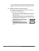
þ
To configure the instantaneous system inertia function block:
▲
Set
BUILDUP
CONSTANT
(P.871), which is a per-normal value of product density,
using the following calculation:
N
=
BUILDUP
CONSTANT
= (
JBAR
I
/
JBAR
)-1 /(
DBAR
i
4
-1)
WDBAR
l
Where:
•
JBAR
I
= time to accelerate a roll, whose diameter I can be anywhere
between core and full roll, to base speed with full shunt field excitation. Note
that speed loop self-tuning can be used to determine
JBAR
I
; however, once the
value is extracted, the speed loop self-tuning should be set to a final value for
JBAR
, which is identified as
SYSTEM
INERTIA
(P.222).
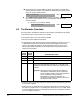
Use This Chapter for These Applications:
•
Variable Diameter Speed Regulator
•
Variable Diameter Current Regulator
•
Variable Diameter Position Regulator
•
Variable Diameter Tension Regulator
•
Generic