WebPak 3000 DC Drive Application Workbook Version 1.
The information in this manual is subject to change without notice. Throughout this manual, the following notes are used to alert you to safety considerations: ! ATTENTION: Identifies information about practices or circumstances that can lead to personal injury or death, property damage, or economic loss. Important: Identifies information that is critical for successful application and understanding of the product.
CONTENTS Contents Chapter 1 Getting Started 1.1 Where to Find Additional Information .............................................................. 1-1 1.2 Getting Assistance from Reliance Electric....................................................... 1-2 Chapter 2 How to Use This Manual 2.1 If You Are Using WebPakCS Software to Configure the Drive........................ 2-1 2.2 If You Are Using the OIM to Configure the Drive............................................. 2-1 2.3 About Scaling ........
Chapter 8 Configuring Losses Compensation Chapter 9 Configuring the Outer Control Loop Reference 9.1 The Tension Setpoint .......................................................................................9-1 9.1.1 Stall Tension Mode ................................................................................9-2 9.1.2 The Taper Function................................................................................9-3 9.1.3 The Taper Type ..........................................................
List of Figures Figure 3.1 – Outer Control Loop Proportional Trim ................................................ 3-11 List of Tables Table 2.1 – Locating the Appropriate Chapters for Your Application........................
IV WebPak 3000 DC Drive Application Workbook, Version 1.
CHAPTER 1 Getting Started ! ATTENTION: WebPak 3000 DC drive parameters must be configured by a qualified person who understands the significance of configuring them accurately. Failure to observe this precaution could result in severe bodily injury or loss of life. This manual provides guidance in configuring the WebPak 3000 DC drive for web-handling applications. What You Need to Know • You must be qualified to program the drive and be familiar with web-handling applications.
1.2 Getting Assistance from Reliance Electric If you have any questions or problems with the products described in this instruction manual, contact your local Reliance Electric sales office. For technical assistance, call 1-800-726-8112. 1-2 WebPak 3000 DC Drive Application Workbook, Version 1.
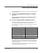
CHAPTER 2 How to Use This Manual This manual provides configuration guidance for users of the OIM and the WebPakCS Configuration Software. 2.1 If You Are Using WebPakCS Software to Configure the Drive The chapter titles in this manual correspond to the screen selections available in the WebPakCS software. Each chapter guides you through the parameters as they appear on the screens. 2.2 If You Are Using the OIM to Configure the Drive Use table 2.
2.3 About Scaling The WebPak 3000 drive follows the scaling conventions described in sections 2.3.1 and 2.3.2. 2.3.1 For Position Loops The dancer feedback should be scaled so that 0 to 4095 counts corresponds to 0 to full storage as defined by the parameter STORAGE (P.857). The midpoint of the dancer travel should correspond to 2048 counts. 2.3.2 For Current and Tension Loops The current and tension outer loops are scaled so that 4095 counts corresponds to rated tension.
CHAPTER 3 Configuring the Speed Loop Use This Chapter for These Applications: • • • • • • • • • Constant Diameter Speed Regulator Variable Diameter Speed Regulator Constant Diameter Current Regulator Variable Diameter Current Regulator Constant Diameter Position Regulator Variable Diameter Position Regulator Constant Diameter Tension Regulator Variable Diameter Tension Regulator Generic The WebPak 3000 drive can be configured as a speed regulator or as an armature voltage regulator, depending on the valu
3.1 The Speed Loop Reference Refer to figure A.4 in Appendix A of the software manual (D2-3444) as you set up the speed loop reference. The setup of the speed reference depends on the control source selected. The control source selections are: KEYPAD - The drive uses the reference from the OIM. Important: If you select KEYPAD as the control source, the drive can be used to regulate speed only. TERMBLK - The drive uses the reference from the Regulator board terminal strip.
▲ Set LINE SPEED ZERO ADJ (P.102) to adjust the zero point of the line speed reference input to remove any offset from the input signal. Range: -200 to 200 COUNTS ▲ P.102 = COUNTS Set TOP LINE SPEED (P.020). ATTENTION: Do not allow the motor to exceed the maximum safe speed of the motor or driven equipment as determined by the equipment manufacturer. Failure to observe this precaution could result in bodily injury. ! Range: 0 to 5000 FPM P.020 = FPM LINE SPEED (P.
1, 2, 3 - The trim reference signal is based on network input register 1, 2, or 3 if the control source (P.000) = NETWORK. (Available only if a communication option board is installed.) NETW IN REG Range: REGISTER, ANALOG, NETW IN REG 1, 2, 3 þ If TRIM REFERENCE SELECT (P.108) = REGISTER: ▲ Set TRIM REF REGISTER (P.107). P.107 = Range: +/-100.0% þ P.108 = % If TRIM REFERENCE SELECT (P.108) = ANALOG ▲ If necessary, adjust the gain using DIAMETER/TAPER GAIN (P.104). Range: 0.750 to 2.250 ▲ P.
þ To configure the speed reference ramp: ▲ Set TRIM MODE SELECT (P.110). The choices are: NO TRIM - Used when the drive is configured as: • a stand-alone speed-regulated section • a lead or master section of a process • an inner speed loop as part of major outer control loop design. - Depending on the polarity of the trim reference, adds or subtracts from the speed reference a constant value that is derived from TOP LINE SPEED (P.020).
▲ Leave DIAMETER REGISTER (P.874) at its default value of 1.000. P.874 = Range: 1.000 to 20.000 þ To modify the results of the LIMIT block using REVERSE DISABLE (P.015). ▲ Set REVERSE DISABLE (P.015). The choices are: - Prevents the speed reference from going below zero (prohibits the drive from operating in the opposite direction). ON - (Default) Allows the speed reference to go below zero (allows the drive to operate in the opposite direction). OFF P.
ABOUT SPEED PARAMETERS It is important to understand the relationship of the following speed-defined parameters: TOP LINE SPEED (P.020) is the maximum speed of the drive in length per time; for example, feet per minute. GEAR IN SPEED (P.011) is the motor speed in RPM that results in TOP LINE SPEED (P.020). If the section is a center-driven unwind or winder (variable diameter), GEAR IN SPEED is the motor RPM that results in TOP LINE SPEED at EMPTY CORE DIAMETER (P.830). MAXIMUM SPEED (P.
3.2.2 The S-CURVE Block The output of the LIMIT block is the input to the S-CURVE block. SPEED RAMP BYPASS (P.112) controls the output of the S-CURVE block. Refer to figure A.5 in Appendix A of the software manual (D2-3444). þ To set up the S-CURVE block: ▲ Set SPEED RAMP BYPASS (P.112). The choices are: - Bypasses the S-CURVE block, and the output of the LIMIT block is used as the value of SPEED RAMP OUTPUT (P.199). (This value can also be read as SPEED RAMP INPUT TP (P.198)).
The choices for STOP DECEL SELECT (P.122) are: (P.002) - The ramp stop deceleration time is controlled by P.002, which was set during Quick Start. DECELERATION TIME (P.018) - The ramp stop deceleration time is controlled by P.018. Note that the S-CURVE function is disabled if P.108 is selected. RAMP STOP DECEL TIME Range: P.002, P.018 þ P.122 = If STOP DECEL SELECT (P.122) = P.018: ▲ Set RAMP STOP DECEL TIME (P.018). Range: 0.1 to 300.0 SECONDS P.018 = SECONDS ▲ Set STOP SPEED THRESHOLD (P.
• Selecting the outer loop type Refer to figure A.6 in Appendix A of the software manual (D2-3444). 3.3.1 Configuring Jog ATTENTION: This drive can operate at and maintain zero speed when JOG SPEED (P.012) is set to zero. A voltage-regulated drive can produce zero speed at low minimum speed values.
þ To select the outer control loop proportional trim operation: The value of the outer control loop PI limits is set proportional to the absolute value of SPEED RAMP OUTPUT (P.199). This keeps the gain of the outer control loop constant at all line speed operating levels. A SCALE block is used to establish the range of the outer control loop percent control. The output of the SCALE block will be a number that will change linearly from the value of OCL PROP TRIM GAIN (P.812) to 1.0 as SPEED RAMP OUTPUT (P.
3.3.3 Selecting the Outer Loop Type þ To select the outer loop type: ▲ Set OCL TYPE (P.818). The choices are: - The outer control loop trim signal is added to the speed loop reference. The dynamics of the outer control loop and the inner speed loop are interactive in the cascade mode. CASCADE PARALLEL - The outer control loop trim signal is used as the input level for both the high and low current limits of the speed loop PI block.
(P.295) is the composite signal configured by the various modes listed in this section. The final value of P.295 is clamped at + or – 110% of TOP LINE SPEED (P.020). If REVERSE DISABLE (P.015) = ON, SPD LOOP REFERENCE (P.295) is prevented from setting a reverse reference by clamping this reference to zero. SPD LOOP REFERENCE 3.4 Speed Loop Feedback Refer to figure A.10 in Appendix A of the software manual (D2-3444) as you configure the speed loop feedback.
▲ Set SPD LEADLAG SELECT (P.216) to compensate for backlash in the drive-train gears and couplings. The choices are: LEAD/LAG - SPD LEADLAG LOW FREQ (P.214) specifies the lag break frequency. BYPASS - The lead/lag block is bypassed and the feedback signal is used directly by the speed loop summing junction. LAG/LEAD - SPD LEADLAG LOW FREQ (P.214) specifies the lead break frequency. P.216 = Range: LEAD/LAG, BYPASS, LAG/LEAD þ If SPD LEADLAG SELECT (P.
þ If SPEED PROFILER ENABLE (P.127) = ENABLE: ▲ Set SPD LOOP PI PROP GAIN (P.211). This value is determined during speed loop self-tuning. Range: 0.10 to 128.00 ▲ Set SPD LOOP PI LEAD FREQ (P.212). This value is determined during speed loop self-tuning. Range: 0.00 to 141.37 RAD/S ▲ P.212 = RAD/S Set SYSTEM INERTIA (P.222). System inertia (called JBAR in the gain profiler block) is the time, in seconds, to accelerate an empty core to the motor base speed parameter, BASE SPEED (P.
▲ Set NEG CURRENT LIMIT SEL (P.224). The choices are: REGISTER - NEGATIVE CURRENT LIM (P.006) is used as the negative current limit. PARALLEL OCL - Sets the limits to the value of OCL PARALLEL OUT (P.816) which is the vernier signal of the selected outer control loop. 1, 2, 3 - Sets the limit values in network registers if a network card is installed and the control source is NETWORK (P.000 = NETWORK). NETW IN REG Range: REGISTER, PARALLEL OCL, NETW IN REG 1, 2, 3 þ P.
3.5.2 The Current Memory Function The transfer dynamics of some unwind and winder designs will require an operating mode change from the primary outer control loop regulator to an interim current loop regulator. This regulator transition is necessary when the primary loop regulator feedback device (load cell or dancer) becomes mechanically isolated at some point in the transfer sequence. The current memory function places the drive in a current regulator mode with a fixed reference.
3-18 WebPak 3000 DC Drive Application Workbook, Version 1.
CHAPTER 4 Configuring the Current Minor Loop Use This Chapter for These Applications: • • • • • • • • • Constant Diameter Speed Regulator Variable Diameter Speed Regulator Constant Diameter Current Regulator Variable Diameter Current Regulator Constant Diameter Position Regulator Variable Diameter Position Regulator Constant Diameter Tension Regulator Variable Diameter Tension Regulator Generic The current minor loop (CML) regulates the amount of current flowing through the motor armature.
The composite CML reference signal, read as CML RAMP INPUT TP (P.390), passes through an amplitude limit block and a rate limit block. The amplitude limit block prevents the reference signal from becoming greater than or less than the limits selected by CML REF LIMIT SELECT (P.311). The rate limit block limits the rate of change of the selected CML reference based on the value you input for CML REF RATE LIMIT (P.303).
▲ Set CML REF LIMIT SELECT (P.311) to select the source for the CML HI (positive) and LO (negative) current limits. The choices are: SPD LOOP PI LIMITS - The CML loop reference limits are the same as those used by the speed loop PI block. REGISTER - The CML loop limits are POSITIVE CURRENT LIM (P.005) and NEGATIVE (P.006). CURRENT LIM Range: SPD LOOP PI LIMITS, REGISTER þ P.311 = If CML REF LIMIT SELECT (P.311) = REGISTER and you want NEGATIVE CURRENT LIMIT (P.006) and POSITIVE CURRENT LIMIT (P.
Note the following design features: • Network logic will switch between current and speed regulation by activating bit 11 of the network command word. • If a network kit is installed, the control source is NETWORK, and P.811 is set to DISABLE, the drive will operate according to the status of jumper J15. • If a network kit is not installed, drive operation will revert back to the status of jumper J15, ignoring the status of P.811. NETWORK KIT (P.
▲ Set or verify CT TURNS RATIO (P.010). ! ATTENTION: The CT TURNS RATIO (P.010) parameter is used in the calculation of the burden resistor value. Do not change this parameter from its factory default value unless you are replacing the Regulator board. Failure to observe this precaution could result in damage to, or destruction of, the equipment. Range: FACTORY SET; SEE SOFTWARE MANUAL (D2-3444) P.010 = J18 ARM I FB RESISTOR (P.
4-6 WebPak 3000 DC Drive Application Workbook, Version 1.
CHAPTER 5 Configuring the Field Current Regulator Use This Chapter for These Applications: • • • • • • • • • Constant Diameter Speed Regulator Variable Diameter Speed Regulator Constant Diameter Current Regulator Variable Diameter Current Regulator Constant Diameter Position Regulator Variable Diameter Position Regulator Constant Diameter Tension Regulator Variable Diameter Tension Regulator Generic Configuring the field current regulator consists of setting up the following: • Field reference • Field f
If FIELD ECONOMY ACTIVE (P.599) = ON, the field economy function is enabled. The value of the reduced field voltage is a percentage of MOTOR HOT FLD AMPS (P.510) as determined by the output of a multiplier block that multiplies P.510 by FIELD ECONOMY REF (P.511). FIELD ECONOMY DELAY (P.501) will, after the motor stops, hold the field voltage at its normal operating level for the time set by P.501, before entering field economy. If FIELD ECONOMY ACTIVE = OFF, the field economy function is bypassed.
▲ Set FIELD SHAPING TYPE (P.539). The choices are: SPEED - The index values are tabled to follow the absolute value of motor rotational speed by multiplying the absolute value of SPD SOURCE SELECT OUT (P.193) with NORM ROLL DIAMETER (P.131). The product is limited to a high value of GEAR IN SPEED (P.011) and a low value of MOTOR SPD AT MAX FLD (P.540), which typically is the motor speed with the motor field excitation set at MOTOR HOT FLD AMPS (P.510).
▲ Set FIELD INPUT 8 (P.537). Range: 0 to 5000 RPM ▲ P.525 = AMPS P.526 = AMPS P.527 = AMPS P.528 = AMPS P.529 = AMPS Set FIELD CURRENT 8 (P.529). Range: 0.00 to MOTOR HOT FLD AMPS (P.510) ▲ AMPS Set FIELD CURRENT 7 (P.528). Range: 0.00 to MOTOR HOT FLD AMPS (P.510) ▲ P.524 = Set FIELD CURRENT 6 (P.527). Range: 0.00 to MOTOR HOT FLD AMPS (P.510) ▲ AMPS Set FIELD CURRENT 5 (P.526). Range: 0.00 to MOTOR HOT FLD AMPS (P.510) ▲ P.523 = Set FIELD CURRENT 4 (P.525). Range: 0.
5.2 The Field Feedback FIELD FEEDBACK (P.589) is derived from field current being fed into an analog input and scaled by MOTOR HOT FLD AMPS (P.510) and FLD FEEDBACK GAIN ADJ (P.516). Refer to figure A.12 in Appendix A of the software manual (D2-3444). þ To configure field feedback: ▲ Set FLD FEEDBACK GAIN ADJ (P.516). Range: 0.900 to 1.100 5.3 P.
▲ Refer to the WebPak 3000 software manual (D2-3444) for the descriptions of the following parameters and adjust them to tune the field control loop if necessary. • FLD WEAKEN THRESHOLD (P.518). Range: 0 to 120% of P.009 • FLD WEAKEN LEAD FREQ FLD WEAKEN PROP GAIN Range: 0.01 to 128.00 5.4 % P.520 = RAD/S (P.520). Range: 0.00 to 56.54 RAD/S • P.518 = (P.519). P.519 = The Field Regulator The field current regulator operates closed loop with a PI amplifier block. FIELD DELTA (P.
CHAPTER 6 Configuring the Diameter Calculator Use This Chapter for These Applications: • • • • • Variable Diameter Speed Regulator Variable Diameter Current Regulator Variable Diameter Position Regulator Variable Diameter Tension Regulator Generic For variable diameter applications, typically unwinds and winders, the diameter calculator supports diameter-sensitive drive tasks such as stability, inertia compensation, motor field profiling and taper tension.
▲ Set DIAMETER UPDATE RATE (P.867) to specify the number of roll revolutions between diameter updates. This is based on web thickness. Typically, thinner webs use a higher update number. P.867 = Range: 1 to 10 REVOLUTIONS þ For variable diameter applications (unwinds or winders), GEAR IN SPEED (P.011) is the motor speed at TOP LINE SPEED (P.020) and EMPTY CORE DIAMETER (P.830): ▲ Set EMPTY CORE DIAMETER (P.830). Range: 1.00 to 30.00 INCHES 6.2 REV P.
The remaining inputs are user configurable. þ To configure the diameter calculator function: ▲ Set WINDER CORE DIA 1 (P.822). Range: 1.00 to 120.00 INCHES P.822 = INCHES P.824 = INCHES P.825 = INCHES P.830 = INCHES P.125 = INCHES ▲ Set WINDER CORE DIA 2 (P.824). Range:1.00 to 120.00 INCHES ▲ Set WINDER CORE DIA 3 (P.825). Range: 1.00 to 120.00 INCHES ▲ Set EMPTY CORE DIAMETER (P.830). Range: 1.00 to 30.00 INCHES ▲ Set FULL ROLL DIAMETER (P.125). Range: P.830 to 120.
• NORM ROLL DIAMETER (P.131) is the calculated roll diameter normalized to 1.000 at EMPTY CORE DIAMETER (P.830). A limit block and a rate block condition the final value of NORM ROLL DIAMETER (P.131), which is used as an input parameter in other drive tasks. 6.2.1 Validating the Setup of the Diameter Calculator þ To validate the setup and operation of the diameter calculator without an actual buildup of a variable diameter roll: ▲ Set DIAMETER CALC ENABLE (P.826) to DISABLE.
CHAPTER 7 Configuring Inertia Compensation Use This Chapter for These Applications: • • • • • Variable Diameter Speed Regulator Variable Diameter Current Regulator Variable Diameter Position Regulator Variable Diameter Tension Regulator Generic Inertia compensation provides the change in motor torque required during acceleration and deceleration to minimize transient error of the controlled process variable.
• JBAR = time to accelerate an empty core to base speed with full shunt field excitation. The results of speed loop self tuning should yield a value for JBAR in SYSTEM INERTIA (P.
▲ Set INERTIA GAIN ACCEL (P.245). Typically, this is left at its default value of 1 but may need to be adjusted if inertia is not equal in both directions. Range: 0.10 to 10.00 P.245 = ▲ Set INERTIA GAIN DECEL (P.229). Typically, this is left at its default value of 1 but may need to be adjusted if inertia is not equal in both directions. Range: 0.10 to 10.00 P.229 = (P.245) and INERTIA GAIN DECEL (P.229) support the setting of separate levels of inertia compensation for acceleration and deceleration.
7-4 WebPak 3000 DC Drive Application Workbook, Version 1.
CHAPTER 8 Configuring Losses Compensation Use This Chapter for These Applications: • • • • • • • • Constant Diameter Speed Regulator Variable Diameter Speed Regulator Constant Diameter Current Regulator Variable Diameter Current Regulator Variable Diameter Position Regulator Constant Diameter Tension Regulator Variable Diameter Tension Regulator Generic When a current regulator is used to control tension or to support load share profiling, its performance will be enhanced by the application of friction a
▲ Run the drive as a speed regulator long enough to stabilize the mechanical characteristics of the load (bearings, couplings, etc.). ▲ Set the speed reference to 10% of TOP LINE SPEED (P.020). ▲ Run the drive and adjust FRICTION LOSS (P.123) until the speed loop PI output SPD LOOP OUTPUT Range: 0.0 to 50.0% (P.299) is zero. P.123 = % ▲ Set the speed reference to 100% of TOP LINE SPEED (P.020). ▲ Run the drive and adjust WINDAGE LOSS (P.243) until SPD LOOP OUTPUT (P.299) is zero. Range: 0.0 to 50.
CHAPTER 9 Configuring the Outer Control Loop Reference Use This Chapter for These Applications: • • • • • • • Constant Diameter Current Regulator (Section 9.1) Variable Diameter Current Regulator (Section 9.1) Constant Diameter Position Regulator Variable Diameter Position Regulator Constant Diameter Tension Regulator (Section 9.1) Variable Diameter Tension Regulator (Section 9.
þ If TENSION SETPOINT SEL (P.855) = REGISTER: ▲ Set TENSION SETPOINT (P.854). Range: 0 to 4095 COUNTS (4095 COUNTS = RATED TENSION) þ P.854 = COUNTS If TENSION SETPOINT SEL (P.855) = ANALOG: ▲ Set TENSION SETPT SIG TYPE (P.413). Range: 0 to 10 V, +/-10 V, 4 to 20 mA, 10 to 50 mA ▲ Set TENSION SETPOINT ZERO (P.414). P.414 = Range: -200 to 200 COUNTS ▲ P.413 = COUNTS Set TENSION SETPOINT GAIN (P.415). P.415 = Range: 0.750 to 2.250 TENSION SETPOINT IN (P.
9.1.2 The Taper Function þ To implement a taper function for winder tension profiling with roll buildup: The section run input and the tension on input must be asserted. ▲ Set TAPER ENABLE (P.858) to ENABLE. This will modify the tension reference based on the dynamic value of TAPER PERCENT (P.859) which is the product of (P.862) and TAPER TYPE (P.863). (See section 9.1.3, Taper Type.) TAPER SET SELECT P.858 = Range: ENABLE, DISABLE (1$%/( ▲ Set TAPER SET SELECT (P.
The linear function is based on the equation: Taper Percent = (Instantaneous Roll Dia. – Empty Core Dia.) / (Full Roll Dia. – Empty Core Dia.) HYPERBOLIC - Provides a taper profile decreasing from core to full roll based on the equation: Taper Percent = (1- Empty Core Dia. / Instantaneous Roll Dia.) / (1 – Empty Core Dia. / Full Roll Dia.) TAPER REGISTER - Provides the capability to generate the taper curve external to the WebPak 3000 drive and input the curve over the network interface.
▲ Set ANLG OUT 3 SIG TYPE (P.419) to 0 to 10 volts or 4 to 20 mA, depending on the type of input signal the dancer transducer requires. Range: 0 to 10 V, +/-10V, 4 to 20 mA, 10 to 50 mA P.419 = ▲ Set ANLG OUT 3 GAIN ADJ (P.420) to specify the maximum value of the analog output when the dancer loading input is at its maximum. Range: .500 to 1.300 P.420 = DANCER LOADING SETUP EXAMPLE Assumptions: • When TENSION SETPOINT (P.854) is set to MAXIMUM, TENSION DEMAND (P.844) is at 4095 counts.
9-6 WebPak 3000 DC Drive Application Workbook, Verson 1.
CHAPTER 10 Configuring the Current Major Outer Control Loop Use This Chapter for These Applications: • • • Constant Diameter Current Regulator Variable Diameter Current Regulator Generic The current major outer control loop uses the same RATELIM and PI control blocks as the tension outer control loop.
• SPEED CROSS OVER (P.133), which is the bandwidth of the speed loop. This parameter is one of the outputs calculated by the speed loop gain profiler block. The remaining inputs are user configurable. þ To configure the gain profiler block: ▲ Set TEN PROFILER ENABLE (P.878). The choices are: - The value of TEN PI KP OUT (P.879) is the output of the gain profiler block. (TEN PI KP OUT (P.879) is the value of the proportional gain applied to the current major loop regulator PI block.) Set P.
Three of the inputs to the tension-to-current scaling block are calculated by the system: • NORM FIELD REF (P.130) is the normalized field reference input to the field shaping task. • NORM ROLL DIAMETER (P.131) is the normalized roll diameter output of the diameter calculator table. • Normalized full roll diameter, which is the calculated value of roll buildup. The remaining input is user configurable: ▲ Set MAXIMUM CURRENT (P.
Note that TENSION VERNIER (P.856) will be a proportional or incremental trim of line speed dependent on the configuration of OCL PROP TRIM SELECT (P.813). Refer to section 3.3 and figure 3.1. þ To set the PI block HI and LO limits: ▲ Set TENSION PI LIMIT (P.853). For example, if 10% tension vernier is to be used, set the PI block HI and LO limits to 409 counts. The output of the tension PI block provides a vernier signal that is used to trim the speed loop reference when OCL TYPE (P.
10.6 Validating the Settings of TEN PI PROP GAIN (P.841) and TEN PI LEAD FREQ (P.840) This section describes how to verify the dynamic performance of the drive with web in the machine. Important: The parameters listed in the procedure below are adjusted specifically for this procedure and then are reset to their previous values. Use the blanks to record the values of the parameters before the validation procedure is performed. þ To validate the settings of the PI proportional gain (P.
! ATTENTION: Depending on machine losses, the 5% current step required in the next step may accelerate the motor above 20% line speed. The user must be ready to shut the drive down in case of overspeed. Failure to observe this precaution could result in severe bodily injury or loss of life. ▲ Assert the TENSION ON digital input to step the current reference 5%. ▲ Set ANLG OUT 1 SELECT (P.404) to CML FEEDBACK, and connect the analog output signal to a oscilloscope or strip chart recorder.
CHAPTER 11 Configuring the Position Outer Loop Use This Chapter for These Applications: • • • Constant Diameter Position Regulator Variable Diameter Position Regulator Generic The position outer control loop includes: • Position gain profiler • Position PI input • Position PI output • Type 3 position regulator þ To select the position outer loop: ▲ Set OCL SELECT (P.817) to POSITION. Range: NONE, TENSION, CURRENT, POSITION P.817 = 326,7,21 Refer to figure A.
▲ Set STORAGE (P.857) to equal the amount of material in feet that can be stored in the dancer over which the position feedback varies from 0 to maximum. P.857 = Range: 0.0 to 10.0 FEET FEET ▲ Set TOP LINE SPEED (P.020) to specify the maximum machine speed in feet per minute. Note that the units of length must be the same as the units used for (P.857). STORAGE P.020 = Range: 0 to 5000 FPM FPM ▲ Set POSITION CROSS OVER (P.239) to specify the crossover frequency of the position loop.
▲ Set POS PI PROP GAIN (P.236) using the same test formula as for KP as shown at the end of this section. P.236 becomes the value for P.248. P.236 = Range: 0.10 to 128.00 ▲ Set POS PI LEAD FREQ (P.234) to 0.2 radians/seconds. P.234 becomes the value for P.249. Range: 0.00 to 141.37 RAD/S P.234 = 5$' 6 ▲ Set POS LEADLAG LOW FREQ (P.231) to the same value as SPEED CROSS OVER (P.133). P.231 becomes the value for P.246. Range: 1.00 to 34.90 RAD/S RAD/S P.231 = ▲ Set POS LEADLAG RATIO (P.232) to 7.5.
11.2 The Position PI Input The input to the position PI block is the rate-limited value of POSITION REFERENCE (P.240). The input to the RATELIM block is P.240, the output is POS RAMP OUTPUT (P.237). þ To configure the position PI block input: ▲ Set POSITION REFERENCE (P.240) to specify the dancer position reference in counts. The value in P.240 defines the dancer loop position during steady state operation, which would normally be the midpoint of the dancer storage (typically 2048 counts).
The output of the SCALE block is TEN/DANCER FDBK SCALED (P.489). See the following examples for more information on setting up the SCALE block. Setting Up the Scale Block The setting for TENSION FDBK MIN (P.852) and TENSION FDBK MAX (P.851) depend on the characteristics of the dancer feedback signal. The output of the SCALE block will go from 0 to 4095 counts as the dancer goes from zero storage to maximum storage.
11.4 Type 3 Position Regulator ! ATTENTION: The J15 jumper must be set to the torque/current position when using the WebPak 3000 drive’s type 3 position loop feature. Applying a drive as a direct current regulator has safety issues that must be considered. Failure to observe this precaution could result in severe bodily injury or loss of life. The drive’s type 3 position regulator feature bypasses the speed loop, which eliminates the need to provide a motor speed feedback device.
CHAPTER 12 Configuring the Tension Outer Control Loop Use This Chapter for These Applications: • • • Constant Diameter Tension Regulator Variable Diameter Tension Regulator Generic The tension outer control loop regulator uses the same RATELIM and PI control blocks as the current major outer control loop. The tension output control loop includes: • Tension PI input • Tension PI limits • Tension PI output þ To select the tension outer control loop: ▲ Set OCL SELECT (P.817) to TENSION.
▲ Set TENSION/DANCER GAIN (P.417) to adjust the gain of the analog input signal if necessary. P.417 = Range: 0.750 to 2.250 ▲ If necessary, set TENSION/DANCER ZERO (P.416) to adjust the zero point of the analog input signal. Range: -3000 to 3000 P.416 = TENSION/DANCER FDBK (P.493) feedback to the PI block.
12.1.2 The LEAD/LAG Block The tension feedback signal is also conditioned by a LEAD/LAG block, which is set to approximately cancel the lag attributable to the speed loop bandwidth. Refer to figure A.18 in Appendix A of the software manual (D2-3444). þ To set up the LEAD/LAG block: ▲ Set TEN FDBK LL BYPASS (P.845) to OFF. Range: OFF, ON P.845 = 2)) ▲ Set TEN FDBK LL LOW FREQ (P.835) to the same value as SPEED CROSS OVER (P.133). Range: 0.01 to 34.90 RAD/S P.835 = RAD/S ▲ Set TEN FDBK LL RATIO (P.
! ATTENTION: The user must read and understand the drive sequencing description and state diagram (figure 3.3 in the WebPak 3000 software manual, D2-3444) before using the TENSION ON input. Setting OCL SELECT (P.817) to any option but NONE permits the TENSION ON input to start the drive. Once the TENSION ON input is permitted to start the drive, negating the TENSION ON input while in any state other than the stall tension state will not stop the drive.
12.1.4 Dynamic Gain Profiling (Variable Diameter Applications) It is recommended that all variable diameter tension applications use dynamic gain profiling.The gain profiler calculates the dynamic value for the PI block proportional gain parameter TEN PI KP OUT (P.879). Refer to figure A.19 in Appendix A of the software manual (D2-3444). þ To configure dynamic gain profiling: ▲ Set TEN PROFILER ENABLE (P.878) to ENABLE. Range: ENABLE, DISABLE P.878 = (1$%/( ▲ Set OCL TYPE (P.
þ To set the PI block HI and LO limits: ▲ Set TENSION PI LIMIT (P.853). For example, if 10% tension vernier is to be used, set the PI block HI and LO limits to 409 counts. The output of the tension PI block provides a vernier signal that is used to trim the speed loop reference when OCL TYPE (P.818) is set to CASCADE and to trim the speed loop PI limits when OCL TYPE (P.818) is set to PARALLEL. In cascade, 4095 counts equals top line speed. In parallel, 4095 counts equals maximum current. P.
CHAPTER 13 Configuring Other Parameters Use This Chapter for These Applications: • • • • • • • • • Constant Diameter Speed Regulator Variable Diameter Speed Regulator Constant Diameter Current Regulator Variable Diameter Current Regulator Constant Diameter Position Regulator Variable Diameter Position Regulator Constant Diameter Tension Regulator Variable Diameter Tension Regulator Generic The parameters listed in this section may or may not apply to your application.
Refer to figure A.21 in Appendix A of the software manual (D2-3444) for a block diagram of the analog outputs. The following parameters are used to configure the analog outputs: • ANLG OUT 1 GAIN ADJ (P.400) P.400 = • ANLG OUT 1 ZERO ADJ (P.402) P.402 = • ANLG OUT 1 FILTER EN (P.406) P.406 = • ANLG OUT 2 GAIN ADJ (P.401) P.401 = • ANLG OUT 2 ZERO ADJ (P.403) P.403 = • ANLG OUT 2 SELECT (P.405) P.405 = • ANLG OUT 2 FILTER EN (P.407) P.407 = • ANLG OUT 3 SELECT (P.418) P.
Refer to figure A.21 in the software manual (D2-3444) for a block diagram of the frequency output. Refer to figure A.20 in the software manual for a block diagram of the frequency input. The following parameters are used to configure the frequency I/O: • FREQ IN • FREQ OUT FULL SCALE • FREQ OUT SELECT • FREQ OUT ZERO P.491 = (P.491) (P.427) (P.425) P.427 = P.425 = P.426 = (P.426) 13.
13.6 Armature Voltage Feedback Use the following parameters if necessary to configure the armature voltage feedback. Refer to figure A.10 in the software manual (D2-3444). • ARM VOLTAGE GAIN ADJ • ARM VOLTAGE ZERO ADJ (P.204) P.204 = (P.205) P.205 = 13.7 Underwind Operation Unwind and winder applications can require “over-under operation,” which is simply a way to implement reversing operation as different products are used.
APPENDIX A Using the WebPak 3000 Drive for Web Applications: The Basics Drive system requirements for web-handling process lines cover applications which require both simple speed regulators for pull rolls and complex tension regulators for unwinds and winders with wide ranges of diameter change and tensions. The WebPak 3000 DC drive provides a common drive platform to be used for all sections of the process line without the need for an external controller.
The digital drives applied to these sections are configured as closed-loop speed, current, position, or tension regulators. The section regulator designs have varying levels of complexity dependent on process dynamics and mechanical design. The WebPak 3000 drive is capable of supporting these regulator requirements within the specified design limits. A.
A.2 Application Guidelines Guidelines for the following applications are described in section A.2.1 through A.2.8: • Speed regulators • Current regulators • Position regulators • Tension regulators • Voltage and field control • Diameter calculator • Flying splice unwinds • Flying transfer winders A.2.1 Speed Regulators Most WebPak 3000 drives will be applied using speed loop control. The speed loop operates with either analog tachometer or digital encoder feedback with a 10 ms update rate.
The WebPak 3000 drive operating in open loop tension control provides an update rate of 20 ms and compensates for other machine conditions, such as friction, windage, and inertia. Motor torque demand includes these loads, as well as, the torque demand required to establish the tension reference set point. Profiling these load conditions in the current regulator design improves the accuracy of the open loop tension control system. Friction and windage values are part of the start-up process.
Changing the load by mechanically adjusting the air supply to the pneumatic cylinder will change web tension. However, a voltage-to-pneumatic (E-to-P) controller applied to the pneumatic cylinder air supply will allow web tension to be set remotely by an operator’s device. This electrical setpoint can be programmed to provide a tension profile, such as taper tension for a center winder. Under position regulation, the operating tension range is not limited by the electrical drive system.
A.2.5 Voltage and Field Control A DC drive that can operate in both the constant torque and constant horsepower range of its associated DC motor can provide performance and economic advantages over a voltage-only drive. Once the motor shaft torque requirements of a driven load have been determined, the motor design parameters are based on the mechanical requirements of the load and the performance requirements of the application.
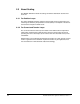
Field Current 1 FIELD CURRENT n 2 3 4 5 6 7 0 FIELD INPUT n 8 GEAR IN SPEED Motor RPM or Roll Diameter Figure A.1 – Typical Type 2 Field Reference Curve A.2.6 Diameter Calculator The need for a diameter calculator function was established under the Type 2 field current regulator design. However, the unwind and winder variable diameter applications require instantaneous diameter information for the additional functions of inertia compensation, taper tension, and control loop gain profiling.
Not all flying splice unwinds will require current memory. On unwinds where the mechanical sequence isolates the outgoing roll from its tension feedback device, current memory would be needed. Current memory may also be used to minimize tension upsets during turret indexing and would be switched into the outgoing roll just before the start of the index. A representative splice sequence follows: • Incoming roll is prepared for splicing with glue pattern or tape.
A representative transfer sequence follows: • The outgoing full roll is indexed to the transfer position, which also places the incoming empty core in position. Current memory could be applied to the outgoing roll during indexing to minimize tension transients. • The incoming core is started and accelerates to surface speed match the web speed. The correct core diameter had been entered as a one of the spindle drive’s setup parameters.
• Jog Fwd - Speed-regulated preset low speed. Used for roll positioning or slack removal. • Jog Rev - Speed-regulated preset low speed. Used for roll positioning or slack removal. • Customer Interlock - Can be used as an external permissive run contact in drive sequence. • Fault Reset - Resets the drive after fault or alarm has occurred. • Tension On - Puts the drive in stall tension if the line is not running. Puts the drive in run tension if the line is running.
A.3.5 Frequency I/O The following frequency input and output are programmed to support the following functions: • Frequency In - Configurable as the line speed reference. 250 kHz maximum frequency. • Frequency Out - Programmed to support the same 31 functions supplied for the analog input. A.
• Drive regulator parameters used to setup and tune the selected control loops, such as, proportional gain, integral gain, current limit, tension on, current memory on, etc. All of these parameters are listed in the Application Workbook. A.4.3 Entering the Parameter Values Parameter values can be entered using either the OIM or the WebPakCS configuration software.
Machine limits can be mechanical or process related. For example, maximum line speed could be limited by maximum roll RPM or by the maximum speed at which a dryer can operate. Drive limits are set based on optimizing drive steady-state and dynamic performance. Refer to table A.2. Table A.2 – Drive Limits Function Mode Limit Limited By Maximum Line Speed All Undefined Machine Minimum Line Speed All 5% of max. Drive Unwind Core Diameter All 1.0 in min.
A.5.2 Steady-State and Dynamic Performance A WebPak 3000 drive section, when applied within the machine parameter limits and set up with the necessary regulator parameters as listed in the Application Workbook, will operate with the following steady-state performance specifications: • Speed regulator with digital encoder feedback • 0.01% of top speed over 20:1 speed range • Speed regulator with analog tach feedback • 1.0% of top speed over 20:1 speed range • Current regulator • 0.
GLOSSARY automatic field weakening (spillover control) - A speed control method that allows the motor to operate throughout the entire constant-torque and constant-horsepower ranges with only one speed control. The field current regulator is controlled by armature voltage. When armature voltage is between zero and 85% of rated voltage, field current is maximum. As armature voltage increases from 85 to 100%, field current is automatically reduced to provide maximum motor speed.
• speed control - Velocity feedback is used when an absolute value of motor shaft speed is required. Shaft speed is measured by a tachometer whose signal is compared to the speed reference signal. • tension control - Tension control systems are used where direct tension measurement is required. The feedback device is a force transducer mounted on each end of a tension-sensing roll.
gain profiling - A function that dynamically adjusts the gains of the speed loop, the tension loop, the current major loop, and the position loop as the response of the system changes due to roll inertia, system losses, and motor torque. geared-in speed - The instantaneous motor speed, taking into account any gearing between the motor shaft and spindle, required to produce the top line speed with an empty core diameter.
loop - A control scheme in which a reference input to a device is compared to a feedback signal from the device for purpose of regulation. Any error is amplified to affect the input to the device to reduce the error. All other “functions” in the loop can be viewed as gain functions. • inner loop - Also known as a “minor loop.” • outer loop - Also known as a “major loop.” losses - A motor converts electrical energy into mechanical energy, and in doing so, encounters losses.
sequencing - Logic that controls the state of the drive (running, stopped, etc.). See chapter 3 in the drive software manual (D2-3444) for more information. slack - Lacking in usual or normal firmness and steadiness; not tight or taut. speed loop - An outer control loop using a speed-sensing device to provide speed feedback for comparison to the speed reference. stall tension - A function that is used to hold a reduced level of tension on the web during a stall condition.
Glossary-6 WebPak 3000 Drive Application Workbook, Version 1.
INDEX A C AC line, 13-3 (P.398), 4-1 CML FEEDBACK (P.397), 3-12, 4-4 CML FEEDBACK GAIN ADJ (P.300), 4-4 CML PI LEAD FREQUENCY (P.302), 4-5 CML PI PROP GAIN (P.301), 4-5 CML RAMP INPUT TP (P.390), 4-2 CML REF LIMIT SELECT (P.311), 4-2, 4-3 CML REF RATE LIMIT (P.303), 4-2, 4-3 CML REFERENCE (P.396), 4-2, 4-3, 4-4 CML SPEED REFERENCE (P.391), 4-1 CONTROL SOURCE SELECT (P.000), 3-2 Control source, selecting, 3-2 CT TURNS RATIO (P.010), 4-4, 4-5 CURRENT COMPOUND TP (P.
Diameter calculator update threshold, configuring, 6-1 DIAMETER DECEL RATE (P.827), 6-3 DIAMETER REGISTER (P.874), 3-6, 6-3, 6-4 DIAMETER RESET TP (P.829), 6-2 DIAMETER RST DIN TP (P.497), 6-2 DIAMETER SELECT A TP (P.495), 6-2 DIAMETER SELECT B TP (P.496), 6-2 DIAMETER UPDATE RATE (P.867), 6-2 DIAMETER/TAPER GAIN (P.104), 3-4, 9-3 DIAMETER/TAPER IN TP (P.192), 6-2, 9-3 DIAMETER/TAPER SELECT (P.870), 6-2, 9-3 DIAMETER/TAPER ZERO (P.105), 3-4, 9-3 DIG OUT 1 CONTACT TYP (P.410), 13-2 DIG OUT 1 SELECT (P.
G L Gain profiler, configuring, 10-1 Gain profiling, configuring, 3-14 GEAR IN SPEED (P.011) configuring speed loop feedback, 3-13 definition, 3-7 diameter calculator update threshold, 6-2 field shaping, 5-3 setting up S-Curve block, 3-9 GEARING (P.
(P.130) configuring losses compensation, 8-1 dynamic gain profiling, 12-5 gain profiler for the current major OCL, 10-1 inertia-to-current scaling, 7-2 tension-to-current scaling, current major OCL, 10-3 NORM ROLL DIAMETER (P.
Setup procedures, overview of, A-11 to A-12 SLACK TAKE UP DIN TP (P.494), 10-4, 12-6 Slack take-up function, 10-4 SLACK TENSION PI LIM (P.318), 10-4, 12-6 SPD LEADLAG LOW FREQ (P.214), 3-14 SPD LEADLAG RATIO (P.213), 3-14 SPD LEADLAG SELECT (P.216), 3-14 SPD LOOP ERROR (P.297), 3-15 SPD LOOP FEEDBACK (P.296), 6-2 SPD LOOP LAG BYPASS (P.217), 3-16 SPD LOOP LAG FREQ (P.215), 3-14, 3-16 SPD LOOP LAG OUTPUT (P.298), 3-16 SPD LOOP OUTPUT (P.299), 3-17, 4-1, 8-2, 10-3 SPD LOOP PI LEAD FREQ (P.
inertia-to-current scaling, 7-2 losses compensation, 8-1 OCL proportional trim, 3-11 position gain profiler, 11-2 speed loop reference, 3-3 speed reference ramp, 3-5 TORQUE REFERENCE (P.189), 4-2 TRIM MODE SELECT (P.110), 3-4, 3-5, 3-8, 3-9 TRIM OUTPUT (P.197), 3-5 TRIM RANGE (P.109), 3-4 TRIM REF REGISTER (P.107), 3-3, 3-4 TRIM REFERENCE SELECT (P.108), 3-3, 3-4 Trim, configuring, 3-3 Type 3 position regulator, 11-6 U (P.877), 13-4 (P.
U.S. Drives Technical Support Tel: (1) 262.512.8176, Fax: (1) 262.512.2222, Email: support@drives.ra.rockwell.com, Online: www.ab.com/support/abdrives Publication D2-3446– June 2000 Copyright © 2000 Rockwell Automation, Inc. All Rights Reserved.