Installation Instructions W-Series Brushless Servo Motor (Catalog Number W-3016-N, W-4030-M, W-4030-P, W-4050-P, and W-4075-R) These installation instructions describe how to install the W-Series motors. Use this document if you are responsible for installing, maintaining, or troubleshooting the Allen-Bradley® W-Series motor products. Please read all instructions before installing the motor.
W-Series Motor Installation Instructions Receiving and Maintenance Information The customer is responsible for inspecting the equipment before accepting the shipment from the freight company. Check the item(s) you receive against your purchase order. Notify the carrier of any shipping damage immediately. W-Series (washdown) motors are designed for long-term use in harsh environments.
W-Series Motor Installation Instructions 3 Before You Install the Motor Before installing or storing the motor: 1. Remove the motor carefully from its shipping container. 2. Visually inspect the motor for any damage. 3. Examine the motor frame, front output shaft, and mounting pilot for any defects. ATTENTION ! Do not open or attempt to open the motor while power is applied to the motor. Only a qualified Allen-Bradley employee can service this type of motor.
W-Series Motor Installation Instructions Guidelines for Installation and Maintenance The following sections provide general installation and maintenance information. The information should assist you to correctly install and to provide maintenance that will prolong the lifetime of your W-Series servo motor. Prolonging Washdown Motor Life Thoughtful design and proper maintenance can increase the life of a washdown motor.
W-Series Motor Installation Instructions 5 Using Couplings and Pulleys Mechanical connections to the motor shaft, such as couplings and pulleys, require a torsionally rigid coupling or a reinforced timing belt. The high dynamic performance of servo motors can cause couplings, pulleys or belts to loosen or slip over time. A loose or slipping connection will cause system instability and may damage the motor shaft.
W-Series Motor Installation Instructions Building and Installing Cables Knowledgeable cable routing and careful cable construction improves system ElectroMagnetic Compatibility (EMC). Refer to Installing Your Motor on page 9 for suggested feedback and power cable trim lengths, and for cable shield grounding at the motor frame. To build and install cables, perform the following steps: 1. Keep wire lengths as short as physically possible. 2.
W-Series Motor Installation Instructions 7 Preventing Electrical Noise ElectroMagnetic Interference (EMI), commonly called noise, may adversely impact motor performance by inducing stray signals. Effective techniques to counter EMI include filtering the AC power, shielding and separating signal carrying lines, and practicing good grounding techniques. Effective AC power filtering can be achieved by using isolated AC power transformers or properly installed AC line filters.
W-Series Motor Installation Instructions Using Shaft Seals A seal is required on the motor shaft near the motor front bearing to reduce exposure to fluids or fine dust that could contaminate the motor bearing and reduce its lifetime. Refer to Motor Catalog Number Identification on page 2 to identify the Frame Size and Shaft Seal type for a particular motor. Refer to Shaft Seals on page 18 for usage information.
W-Series Motor Installation Instructions 9 Installing Your Motor W-Series motors include a mounting pilot for aligning the motor on a machine. Preferred fasteners are stainless steel. The installation must comply with all local regulations and use of equipment and installation practices that promote electromagnetic compatibility (EMC) and safety. ATTENTION ! Unmounted motors, disconnected mechanical couplings, and/or disconnected cables are dangerous if power is applied.
W-Series Motor Installation Instructions To install your motor: 1. Remove the endplate (back cover) of the motor by loosening the screws securing it to the motor housing. IMPORTANT Use care when removing or installing the endplate to avoid damaging the seal. 2. External feedback and power cables must be stripped to a specified length to provide effective electrical contact with the connector without exposing excessive bare wire.
W-Series Motor Installation Instructions 11 5. Seal the motor housing by performing the following sequential steps: a. Position the endplate on the motor while ensuring the cable lengths and routing internal to the motor remain proper. b. Torque the screws securing the endplate to 3.4 Nm (30 in-lb) to seal the motor. c. Turn clockwise the strain relief extension on the plastic cord grips (cable glands) to seal the encoder and power cable openings. 6. Properly mount and align the motor.
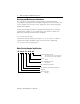
W-Series Motor Installation Instructions Feedback Cable Terminal W-3000 and W-4000 No. or Wire mm (in.) Signal 1 101.60 (4.0) A 2 101.60 (4.0) A3 101.60 (4.0) B 4 101.60 (4.0) B5 101.60 (4.0) I 6 101.60 (4.0) I7 101.60 (4.0) Ground 8 101.60 (4.0) ABS 9 114.30 (4.5) +5VDC 10 114.30 (4.5) COM 11 114.30 (4.5) Hall B 12 114.30 (4.5) Hall C 13 114.30 (4.5) Thermostat 14 114.30 (4.5) Thermostat 15 114.30 (4.5) Hall A Shield 9.53 (0.38) Shield Cable 12.7 (0.50) — Jacket Wire 7.0 (0.
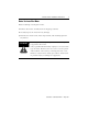
W-Series Motor Installation Instructions 13 Figure 1 W-3000 Cable Connector and Ground Clamp Locations Power Cable Ground Clamp installed between Mounting Dimples Feedback Cable Ground Clamp installed between Mounting Dimples Figure 2 W-4000 Cable Connector and Ground Clamp Locations Feedback Cable Ground Clamp Power Cable Ground Clamp Publication 1398-IN520A-EN-P — May 2001
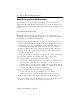
W-Series Motor Installation Instructions Mounting Dimensions The dimension symbols and actual dimensions of the different models in the W-Series are referenced in the table on the next page. Figure 3 Reference Drawing for Mounting Dimensions L N P AK W FULL DEPTH ES Power and Feedback Cable Access through Self-Sealing Plastic Cord Grips in Removable Endplate. Threads are 1/2 inch NPT. Publication 1398-IN520A-EN-P — May 2001 U S BF = DIA. HOLES AJ = DIA. BOLT CIRCLE BD = DIA.
W-Series Motor Installation Instructions Dimension (Refer to drawing) AJ AK BD BF ES L N P S U W Key (supplied) Shaft End Hole Thread Shaft End Hole Thread Depth Tolerances AK L N S U W mm (in.) mm (in.) mm (in.) mm (in.) mm (in.) mm (in.) mm (in.) mm (in.) mm (in.) mm (in.) mm (in.) mm mm mm (in.) mm (in.) mm (in.) mm (in.) mm (in.) mm (in.) mm (in.) Motor Measurement 1 W-3016 W-4030 125.7 145.0 (4.95) (5.71) 80.0 110.0 (3.15) (4.33) 142.0 162.8 (5.59) (6.41) 7.1 10.0 (0.28) (0.39) 20.0 40.0 (0.79) (1.
W-Series Motor Installation Instructions Connector Data The tables below list the signal descriptions for the feedback and power connector terminals.
W-Series Motor Installation Instructions 17 Motor Load Force Ratings Motors are capable of operating with sustained maximum radial or maximum axial shaft loads. The measurement points for maximum radial and axial load forces are shown in the figure below. Figure 4 Load Forces on Shaft Radial load force (FR) Axial load force (F) Radial load force (FR) applied to center of shaft extension The following table represents load factors that provide a 20,000 hour L10 bearing fatigue life for W-Series motors.
W-Series Motor Installation Instructions Shaft Seals Shaft seals that provide environmental sealing of W-Series motors are available from Allen-Bradley. They provide an additional barrier to moisture and particle intrusion to the motor bearings. W-Series motors are shipped with either a Teflon or a Viton shaft seal installed. Using Shaft Seals Teflon shaft seals are primarily for applications above a foodline.
W-Series Motor Installation Instructions 19 To install a new shaft seal: 1. Remove shaft key, if provided. 2. Check the motor shaft and faceplate. Remove nicks and burrs. 3. Protect the seal lip from the sharp edges of the keyway. If necessary, place masking tape over the keyway. 4. Position the seal on the shaft with the sealing lips positioned and slanting outward as shown in Figure 5. If using a Viton shaft seal, lubricant may be applied prior to seating the shaft seal.
W-Series Motor Installation Instructions Shaft Seal Kits Shaft seal kits available from the factory include: Catalog Number Description Applicable Motor 0041-5072 Teflon shaft seal kit for use above foodlines W-3000 0041-5073 Viton shaft seal for use below foodlines 1 0041-5074 Teflon shaft seal kit for use above foodlines 0041-5075 Viton shaft seal for use below foodlines 1 1 W-4000 Lubricant is provided with Viton shaft seal kits.
W-Series Motor Installation Instructions 21 Notes Publication 1398-IN520A-EN-P — May 2001
W-Series Motor Installation Instructions Publication 1398-IN520A-EN-P — May 2001
W-Series Motor Installation Instructions 23 Publication 1398-IN520A-EN-P — May 2001
For more information refer to our web site: www.ab.com/motion Allen-Bradley is a registered trademark of Rockwell Automation. Publication 1398-IN520A-EN-P — May 2001 Supercedes 1398-5.8 April 1999 PN 0013-1063-001 Rev B © 2001 Rockwell International Corporation. Printed in the U.S.A.