
User Manual
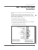


Step 7 - Wire the Control Signal Terminal Block
7-7
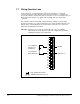
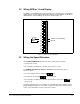
7.4 Wiring RPM or %Load Display
The RPM or %Load Display input (control terminal 12) selects the type of information
displayed by the analog output and the built-in display, speed in RPM or %load. Wire a
switch between control terminals 12 and 13 as shown in figure 7.7.
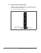
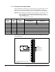
7.5 Wiring the Speed Reference
The
standard VSM500 unit
provides two motor speed reference options:
•
Seven preset speeds
•
An external 0 to 10 VDC or 4 to 20 mA speed reference source
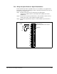
The
VSM500 unit with local operator controls
provides three motor speed
reference options:
•
The local operator controls (using the keys)
•
Seven preset speeds (the keys are not used)
•
An external 0 to 10 VDC or 4 to 20 mA speed reference source (the keys
are not used)
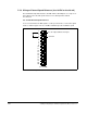
Select the option that is the most suitable for your application. The following sections
provide wiring information for each option except the local operator controls. Refer to
section 1.2 for information on the local operator controls.
Figure 7.7 – RPM or %Load Display Wiring
19
18
17
16
15
14
13
12
11
10
9
8
7
6
5
4
3
2
1
RPM or %Load Display
24V DC
RPM
%Load
20