
Manual


4-4
VSM500 DeviceNet Option Board
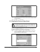
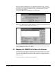
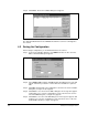
Step 8. Click the new node to highlight it, and then click Edit I/O Parameters. The
Edit Device I/O Parameters dialog box appears.
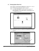
Step 9. Set up the scanner for Polled I/O, Change of State, or Cyclic data exchange.
Refer to your settings for parameter 108 [
INPUT ASSEMBLY] and parameter
107 [
OUTPUT ASSEMBLY] to determine your I/O sizes:
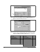
Figure 4.6 – Scan List Editor Dialog Box
Figure 4.7 – Edit Device I/O Parameters Dialog Box
108 - [INPUT ASSEMBLY] Rx Size 107 - [OUTPUT ASSEMBLY]Tx Size
0 = No Data 0 0 = No Data 0
50 = Basic Overload 1 1 = Basic Contactor 1
51 = Extended Overload 1 2 = Two Command Contactor 1
52 = Basic Motor Control 1 3 = Basic Overload 1
53 = Extended Motor Control 1 4 = Basic Motor Control 1
54 = Extended Motor Control 2 1 5 = 2 Command Motor 1
70 = Basic Speed Control 4 20 = Basic Speed Control 4
71 = Extended Speed Control 4 21 = Extended Speed Control 4
100 = Speed Control in Hz 4
106 = Preset Control with Speed 4
î
î