
User Manual

TL-Series Servo Motors 19
Publication TL-IN003A-EN-P — June 2007
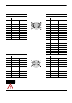
Connector Data
These t ables provide signal descript ions for servo motors with TLY catalog numbers.
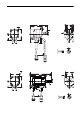
Absolute Encoder Connector Pi nouts Incremental Encoder
Feedback Connections Feedback Connecto r Feedback Connections
Pin Signal Tyco AMP 206152-1 Pin Signal
1…5 Reserved — 1…8 Reserved —
6 BAT+ Brown 9 AM+ Green
7…12 Reserved — 10 AM- Green/blk
13 DATA+ Blue 11 BM+ Blue
14 DATA- Blue/black 12 BM- Blue/blk
15…21 Reserved — 13 IM+ Yellow
22 EPWR 5V Red 14 IM- Yellow/blk
23 ECOM & BAT- Black 15 S1+ Grey/blk
24 SHIELD Drain wire 16 S1- Grey
25…28 Reserved — 17 S2+ Brown/blk
18 S2- Brown
19 S3+ White/blk
20 S3- White
21 Reserved —
22 EPWR 5V Red
23 ECOM Black
24 SHIELD Drain wire
25…28 Reserved —
Power and Brake Connections Power and Brake Connector Power and B rake Connections
Pin Signal Tyco AMP 206705-2 Pin Signal
1 U phase Red 1 U phase Red
2 V phase White 2 V phase Black
3 W phase Black 3 W phase White
4 Reserved — 4 Reserved —
5 Ground Yellow/grn &
drain wires
5 Ground Yellow/grn &
drain wires
6 Reserved — 6 Reserved —
7 MBRK+ Yellow 7 MBRK+ Yellow
8 Reserved — 8 Reserved —
9 MBRK- Blue 9 MBRK- Blue
ATTENTION Be sure that cables are installed and restrained to prevent uneven tension or flexing at
the cable con nect or s. Excessive and uneven forc e at the cable connecto r may resu lt in
damage to the housing and contac ts as the cabl e f lexes. Failure to obser v e t hese saf ety
procedures could result in damage to the motor and its componen ts .
3
14
8
20
28
25
1
9
4
15
26
21
3
6
9
1
4
7