
Owner manual

TL-Series Electric Cylinders 15
Rockwell Automation Publication TLAR-IN001B-EN-P - February 2014
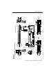
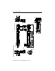
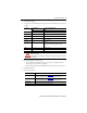
Connector Data
This table lists the signal descriptions for feedback, power, and brake connector pins on the
electric cylinder.
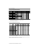
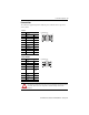
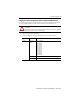
Feedback
Pin Signal Tyco AMP 206152-1
1…5 Reserved —
6 BAT+ Brown
7…12 Reserved —
13 Data+ Blue
14 Data- Blue/black
15…21 Reserved —
22 EPWR 5V Red
23 ECOM & BAT- Black
24 Shield Drain wire
25…28 Reserved —
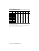
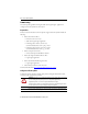
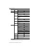
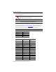
Power and Brake
Pin Signal Tyco AMP 206705-2
1 U phase Red
2 V phase White
3W phase Black
4 Reserved —
5 Ground Yellow/green
and drain
wires
6 Reserved —
7 MBRK+ Yellow
8 Reserved —
9 MBRK- Blue
ATTENTION: Be sure that cables are installed and restrained to prevent uneven tension or flexion at the cable
connectors. Excessive and uneven force at the cable connector can result in damage to the housing and contacts as
the cable flexes. Failure to observe these safety precautions could result in damage to the motor and its
components.
3
14
8
20
28
25
1
9
4
15
26
21
3
6
9
1
4
7