Installation Instructions TL-Series Electric Cylinders Catalog Numbers TLAR-A1xxxB, TLAR-A1xxxE, TLAR-A2xxxC, TLAR-A2xxxF, TLAR-A3xxxE, TLAR-A3xxxH Topic Page Catalog Number Explanation 3 About the TL-Series Electric Cylinders 4 Before You Begin 5 Install the Electric Cylinder 7 Mount the Electric Cylinder 10 Dimensions 11 Connector Data 15 Commissioning 16 Maintenance 29 Storage 30 Troubleshooting 31 Accessories 33 Interconnect Diagrams 37 Additional Resources 41
TL-Series Electric Cylinders Important User Information Read this document and the documents listed in the additional resources section about installation, configuration, and operation of this equipment before you install, configure, operate, or maintain this product. Users are required to familiarize themselves with installation and wiring instructions in addition to requirements of all applicable codes, laws, and standards.
TL-Series Electric Cylinders 3 Catalog Number Explanation Catalog numbers consist of various characters, each identifies a specific version or option for that component. Use the catalog numbering chart below to understand the configuration of your actuator. TL AR - xx xxx x - x x A Motor Mounting (1) A = Axial (in-line) Holding Brake (1) 2 = No Brake 4 = 24V DC Brake Feedback (1) B = Multi-turn, absolute 17-bit encoder, battery backed Mechanical Drive/Screw Lead, Motor Type B = 3.0 mm/rev (0.118 in.
TL-Series Electric Cylinders About the TL-Series Electric Cylinders TL-Series electric cylinders feature multi-turn high resolution encoders and are available with 24V DC brakes. The TL-Series motor rotates a ballscrew drive that converts rotary motion into linear movement. This linear movement results in the piston rod extending and retracting from the electric cylinder housing. IMPORTANT The TLAR-Axxxxx-x2A electric cylinders are non-braking.
TL-Series Electric Cylinders 5 Before You Begin Remove all packing material, wedges, and braces from within and around the item. After unpacking, verify the nameplate catalog number against the purchase order. 1. Remove packaging polyethylene foil and cardboard. The packing materials are recyclable, except for oiled paper that is waste. 2. Remove the electric cylinder carefully from its shipping container. Consider the weight of the electric cylinder.
TL-Series Electric Cylinders • Factory manufactured feedback and power cables are available in standard cable lengths. They provide environmental sealing and shield termination. Contact your Rockwell Automation sales office or refer to the selection guide for cables. Electric Cylinders with Brake Option The brake option on this servo motor is a spring-set holding brake that releases when voltage is applied to the brake coil. A separate power source is required to disengage the brake.
TL-Series Electric Cylinders 7 Preventing Electrical Noise Electromagnetic interference (EMI), commonly called electrical noise, can reduce motor performance. Effective techniques to counter EMI include filtering the AC power, using shielded cables, separating signal cables from power wiring, and practicing good grounding techniques. Follow these guidelines to avoid the effects of EMI: • Isolate the power transformers or install line filters on all AC input power lines.
TL-Series Electric Cylinders ATTENTION: Make sure that cables are installed and restrained to prevent uneven tension or flexion at the cable connectors. Excessive and uneven lateral force at the cable connectors can result in the connector’s environmental seal opening and closing as the cable flexes. Failure to observe these safety precautions could result in damage to the electric cylinder motor and its components.
TL-Series Electric Cylinders 9 4. Attach rod-end accessories and the work load. Be sure the work load center of gravity is centric to the piston rod. ATTENTION: Damage can occur to the electric cylinder bearings and the feedback device if sharp impact to the piston rod is applied during installation. Do not strike the piston rod with tools during installation or removal. Failure to observe these safety precautions could result in damage to the electric cylinder and its components.
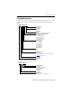
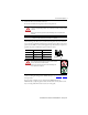
TL-Series Electric Cylinders Mount the Electric Cylinder 1. Use stainless steel fasteners to mount your electric cylinder to your application. 2. Attach power and feedback cables and use a drip loop in the cable to keep liquids away from the motor. Power Connector Feedback Connector Drip Loop BURN HAZARD: Outer surfaces of the motor can reach high temperatures, 65 °C (149 °F), during electric cylinder operation. Take precautions to prevent accidental contact with hot surfaces.
TG Ø30.0 (1.18) d11 Ø16.0 (0.63) h9 12 Flat for Wrench Power/Brake Connector 6.0 (0.24) (x4) E TG E M10x1.25 AM Feedback Connector M6 (x4) 10 L1 See Detail A TL-Series Electric Cylinders (frame 32 and frame 40) Dimensions G ZJ+ L2+ L7 GI Ø16.0 (0.63) Detail A Frame 32 Ø35.0 (1.38) d11 Ø20.0 (0.79) h9 LB + = Plus Stroke Length 16.0 (0.63) M12x1.25 Dimensions ZJ, and L7 are with piston rod is fully retracted. VD WH 1000 (39.4) ±50 (1.97) Dimensions are in mm (in.) 13 Ø16.
TL-Series Electric Cylinders TL-Series Electric Cylinder Dimensions (frame 32) Electric Cylinder Cat. No. L7 (1) mm (in.) LB (1) P AD HD AM G1 L1 ZJ (2) WH mm (in.) mm (in.) mm (in.) mm (in.) mm (in.) mm (in.) mm (in.) mm (in.) mm (in.) TLAR-A1100B-B2A 391.5 (15.41) TLAR-A1200B-B2A 491.5 (19.35) 73.5 (2.89) TLAR-A1300B-B2A 591.5 (23.29) TLAR-A1400B-B2A 691.5 (27.22) TLAR-A1100E-B2A 405.5 (15.96) TLAR-A1200E-B2A 505.5 (19.90) TLAR-A1300E-B2A 605.5 (23.84) TLAR-A1400E-B2A 705.5 (27.
8.0 (0.31) (x4) E Rockwell Automation Publication TLAR-IN001B-EN-P - February 2014 Flat for Wrench Power/Brake Connector TG TG E AM Feedback Connector M8 (x4) L1 See Detail A TL-Series Electric Cylinders (frame 63) G ZJ+ L2+ L7 + = Plus Stroke Length GI Ø45.0 (1.77) d11 Ø28.0 (1.10) h9 20.0 (0.79) Dimensions ZJ, and L7 are with piston rod is fully retracted. VD WH M16x1.50 1000 (39.4) ±50 (1.97) LB 17 Dimensions are in mm (in.) Detail A Frame 63 P Ø17.0 (0.
TL-Series Electric Cylinders TL-Series Electric Cylinder Dimensions (frame 63) Electric Cylinder Cat. No. L7 (1) mm (in.) TLAR-A3100E-B2A 564.6 (22.23) TLAR-A3200E-B2A 664.6 (26.17) TLAR-A3300E-B2A 764.6 (30.10) TLAR-A3400E-B2A 864.6 (34.04) TLAR-A3600E-B2A 1064.6 (41.91) TLAR-A3800E-B2A 1264.6 (49.79) TLAR-A3100H-B2A 564.6 (22.23) TLAR-A3200H-B2A 664.6 (26.17) TLAR-A3300H-B2A 764.6 (30.10) TLAR-A3400H-B2A 864.6 (34.04) TLAR-A3600H-B2A 1064.6 (41.91) TLAR-A3800H-B2A 1264.6 (49.
TL-Series Electric Cylinders 15 Connector Data This table lists the signal descriptions for feedback, power, and brake connector pins on the electric cylinder.
TL-Series Electric Cylinders Commissioning This section provides guidelines for using the Studio 5000 Logix Designer™ application to configure your electric cylinder servo drive system. Required Files Firmware revisions and software versions required to support the electric cylinders include the following: • Kinetix 2000 multi-axis drives – Firmware revision 1.96 or later – Studio 5000 Logix Designer application – For RSLogix 5000™ software, version 16.
TL-Series Electric Cylinders 17 Configure the Logix Designer Application for Electric Cylinder with Kinetix Drives Use the following procedure to configure the drive for your electric cylinder. It is assumed that the electric cylinder and a Kinetix 2000 or Kinetix 350 drive are installed and wired. ATTENTION: Incorrect parameter settings can result in uncontrolled motion, with the potential for damage to the electric cylinder.
TL-Series Electric Cylinders Entry/Selection, with applicable distance unit settings Axis Properties Tab Parameter Conversion Positioning Mode Metric English Linear Setting the Positioning Mode to Rotary can cause damage to the electric cylinder or the machine due to incorrect positioning. Dynamics Conversion Constant 66666.667 drive cnts/1.0 mm for Conversion Constant 20000 drive cnts/1.0 mm for Conversion Constant 40000 drive cnts/1.0 mm for Conversion Constant 15748.0315 drive cnts/1.
TL-Series Electric Cylinders 19 3. Click the Homing tab. 4. Set parameters for either absolute homing or torque level-to-marker homing as shown in the table.
TL-Series Electric Cylinders 8. Set overtravel limits according to the maximum speed of the servo drive system and the payload of the application. ATTENTION: Software overtravel must be set prior to initiating the tuning process. Check the starting position of the piston rod and allow for adequate travel. Insufficient travel while auto tuning causes the software overtravel to trigger or an end-stop impact.
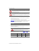
TL-Series Electric Cylinders 21 Cat. No. Extracted Mass g (oz) Impact Velocity, max mm/s (in/s) TLAR-x2200F-xxx 558 (19.7) 26.8 (1.05) TLAR-x2300F-xxx 647 (22.82) 24.9 (0.98) TLAR-x2400F-xxx 736 (26.0). 23.3 (0.92) TLAR-x2600F-xxx 914 (32.2) 20.9 (0.82) TLAR-x3100E-xxx 938 (33.1) 29.2 (1.15 TLAR-x3200E-xxx 1066 (37.6) 27.4 (1.08) TLAR-x3300E-xxx 1194 (42.1) 25.9 (1.02) TLAR-x3400E-xxx 1322 (46.6) 24.6 (0.97) TLAR-x3600E-xxx 1578 (55.7) 22.5 (0.86) TLAR-x3800E-xxx 1834 (64.
TL-Series Electric Cylinders 4. Reduce the default Stopping Time Limit from 10 seconds to 0.5 seconds. IMPORTANT To prevent the rod from moving or falling when installed in a vertical orientation, the Stopping Time Limit must be set to 0.99 seconds or less. 5. Click the Tune tab and enter the following parameters: • Travel Limit - Set to within software limits • Speed (velocity) • Torque/Force IMPORTANT Set travel limits and direction of tuning moves in reference to the piston rod starting position.
TL-Series Electric Cylinders 23 6. Click Start Tuning. The Motion Initiation dialog box is displayed. 7. Click Yes. ATTENTION: Motion occurs immediately after clicking Yes. Tuning is complete when the Tune Servo dialog box appears. 8. Click OK.
TL-Series Electric Cylinders The Tune Results dialog box appears. 9. If you are satisfied with the tuning results, click OK; otherwise, continue with Calculate and Configure the Loop Gain. Calculate and Configure the Loop Gain Calculate a position loop bandwidth based on the actual measured inertia values from the Tune Results dialog box. In this example, the Tune Results dialog box shows a default Position Loop Bandwidth of 45.14153 Hz, and a Load Inertia Ratio of 6.8707952. 1.
TL-Series Electric Cylinders 25 3. Click OK. 4. Click OK on the remaining dialog boxes to apply the values. The proper Position Bandwidth results in a stable starting point; from that you can adjust the gains to fit your application requirements.
TL-Series Electric Cylinders Configure and Tune Your Kinetix 300 Drive for an Electric Cylinder with MotionView On Board Software In this section you use the MotionView Onboard software to configure and tune your electric cylinder. Configure Your Kinetix 300 Drive These steps assume that an electric cylinder and the Kinetix 300 drive are installed and wired as one axis of a motion system.
TL-Series Electric Cylinders 27 9. Enter the Accel Limit, Decel Limit, and the User Units by using values from the following table. User Units can be entered in rev/mm or rev/in. Your choice determines the unit of measure for the axis. Cat. No. Accel/Decel Limits rpm/s User Units rev/mm (rev/in.) TLAR-x1xxxB-Bxx 120000 0.33333 (8.46667) TLAR-x1xxxE-Bxx 36000 0.10000 (2.54000) TLAR-x2xxxC-Bxx 72000 0.20000 (5.08000) TLAR-x2xxxF-Bxx 28346 0.07874 (2.00000) TLAR-x3xxxE-Bxx 36000 0.10000 (2.
TL-Series Electric Cylinders 14. Set overtravel limits according to the maximum speed of the servo drive system and the payload of the application. Set travel limits and direction of tuning moves in reference to the piston rod starting position. Leave adequate travel for the piston rod to complete its moves while tuning. IMPORTANT ATTENTION: Software overtravel must be set prior to initiating the tuning process. Check the starting position of the piston rod and allow for adequate travel.
TL-Series Electric Cylinders 29 The Autotune dialog box appears with the default set to Velocity Tuning. 8. Check Velocity Tuning or Position Tuning or both. 9. Click Start. 10. To accept the new tuning value; click Yes.
TL-Series Electric Cylinders 4. Lightly dampen a soft cloth with isopropyl alcohol and wipe the piston rod and seal. 5. Lubricate the piston rod with a fine layer of LUB-KC1 grease from Klueber, http://www.klueber.com. Storage Store your electric cylinder for a minimal amount of time in a clean and dry location within specifications found in the Kinetix Linear Motion Specifications Technical Data, publication GMC-TD002.
TL-Series Electric Cylinders 31 Troubleshooting Description Possible cause Corrective action Axial play too large. Wear. Replace actuator cylinder. Send to Rockwell Automation for repair. Squeaking noises or vibrations. Distortions. Check the electric cylinder is free of stress and evenly supported ≤ 0.2 mm (0.008 in.). Lubricate piston rod. See Maintenance on page 29. Modify positioning speed. Piston rod does not move. Needs tuning. Modify control parameters.
TL-Series Electric Cylinders Description Possible cause Corrective action Electric cylinder is operating but is not up to rated speeds/forces. Motor phase are wired incorrectly or in incorrect order. Verify correct motor power wiring. Amplifier is improperly tuned. Check gain settings. Amplifier is set up improperly for electric cylinder used. Check amplifier setting for number of poles, voltage, current, resistance, inductance, inertia, and other motor settings.
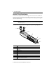
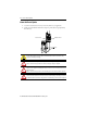
TL-Series Electric Cylinders 33 Accessories The following diagram and tables show the available accessories and their weights. Refer to the Kinetix Motion Control Selection Guide, publication GMC-SG001, for dimensions. 1 13 4 5 8 9 7 11 10 12 6 2 3 4 Mounting Accessories Weight, approx g (oz) Accessory Item 1 2 3 4 6 Foot Mounting Kit 5 Flange Mounting Trunnion Flange Trunnion Support Clevis Foot 32 MPAR-NA174991 240 (8.46) 40 MPAR-NA174992 310 (10.
TL-Series Electric Cylinders TL-Series Electric Cylinders Rod-end Accessories Weight, approx g (oz) Accessory Item Cat. No. Weight, approx g (oz) 10 9 11 Rod Eye 32 MPAR-NE9261 70 (2.47) 8 32 MPAR-NE195582 70 (2.47) 40 MPAR-NE9262 110 (3.53) 63 MPAR-NE9263 210 (7.41) 40 MPAR-NE195583 110 (3.53) 63 MPAR-NE195584 210 (7.41) Rod Clevis 32 MPAR-NE32954 140 (4.94) 32 MPAR-NE6144 110 (3.88) 40 MPAR-NE10767 210 (7.41) 40 MPAR-NE6145 170 (6.00) 63 MPAR-NE10768 500 (17.
TL-Series Electric Cylinders 35 Trunnion Mounting Kit Cat. No. Frame Size Torque N•m (lb•ft) MPAR-NA163525 32 4…5 (2.9…3.7) MPAR-NA163526 40 8…9 (5.9…6.6) MPAR-NA163528 63 18…20 (13.3…14.5) Coupling Piece Attachment Cat. No. Frame Size Max Torque (1) N•m (lb•ft) Max Torque (2) N•m (lb•ft) Max Torque (3) N•m (lb•ft) MPAR-NE36125 32 5.9 (4.35) 34 (25.1) 12 (8.8) MPAR-NE36126 40 5.9 (4.35) 61 (45.0) 22 (16.2) MPAR-NE36127 63 9.9 (7.3) 148 (109.2) 57 (42.
TL-Series Electric Cylinders Weight Specifications Electric Cylinders (weight of cylinder with non-brake motor) Electric Cylinder Cat. No. Weight, approx kg (lb) Electric Cylinder Cat. No. Weight, approx (3) kg (lb) Electric Cylinder Cat. No. Weight, approx (4) kg (lb) TLAR-A1100B-B2A 1.7 (3.75) (1) TLAR-A2100C-B2A 3.1 (6.83) TLAR-A3100E-B2A 9.5 (20.94) TLAR-A1200B-B2A 2.0 (4.41) (1) TLAR-A2200C-B2A 3.6 (7.94) TLAR-A3200E-B2A 10.3 (22.71) TLAR-A1300B-B2A 2.4 (5.
TL-Series Electric Cylinders 37 Interconnect Diagrams This is an example diagram for wiring your TL-Series electric cylinder and Allen-Bradley servo drives.
TL-Series Electric Cylinders Wiring Example of TL-Series Electric Cylinder to Kinetix 300 Drive 2090-CPWM6DF-16AAxx Power Cable without Brake or 2090-CPBM6DF-16Axx Power Cable with Brake Kinetix 300 Servo Drive 0 1 2 3 4 5 6 7 8 9 10 11 12 13 14 15 Motor Power (MP) Connector GREEN/YELLOW BLUE BLACK BROWN W V U TL-Series Electric Cylinder Three Phase Motor Power 5 3 2 1 W V U GND Motor Feedback (MF) Connector Motor Feedback 2090-K2CK-D15M Connector Kit 13 14 BROWN WHT/BROWN DATA+ DATA- 5 10
TL-Series Electric Cylinders 39 Wiring Example of TL-Series Electric Cylinder to Kinetix 350 Drive Kinetix 300 Servo Drive 0 1 2 3 4 5 6 7 8 9 10 11 12 13 14 15 Motor Power (MP) Connector TL-Series Electric Cylinder 2090-CPWM6DF-16AAxx Power Cable without Brake or 2090-CPBM6DF-16Axx Power Cable with Brake GREEN/YELLOW BLUE BLACK BROWN W V U 5 3 2 1 Three Phase Motor Power W V U Motor Feedback (MF) Connector Motor Feedback BLACK BR- WHITE BR+ Brake I/O (IOD) Connector 44 MTR_BRAKEMTR_BRAKE+ 43
TL-Series Electric Cylinders Wiring Example of TL-Series Electric Cylinder to Kinetix 3 Drive Kinetix 3 Servo Drive 0 1 2 3 4 5 Motor Power W 6 (MP) Connector V 7 U 8 9 10 11 Motor Feedback 12 (MF) Connector 13 14 15 16 17 I/O (IOD) 18 Connector 19 20 OUTPUT 3- (BK-) 48 OUTPUT 3+(BK+) 47 2090-CPBM6DF-16AAxx Motor Power and Brake Cable Use 2090-CPWM6DF-16AAxx cable for non-brake applications.
TL-Series Electric Cylinders 41 Additional Resources These documents contain additional information concerning related products from Rockwell Automation. Resource Description TL-Series Servo Motors Installation Instructions, publication TL-IN003 Information on installing TL-Series motors.
TL-Series Electric Cylinders Notes: Rockwell Automation Publication TLAR-IN001B-EN-P - February 2014
TL-Series Electric Cylinders 43 Notes: Rockwell Automation Publication TLAR-IN001B-EN-P - February 2014
Rockwell Automation Support Rockwell Automation provides technical information on the Web to assist you in using its products. At http://www.rockwellautomation.com/support you can find technical and application notes, sample code, and links to software service packs. You can also visit our Support Center at https://rockwellautomation.custhelp.com/ for software updates, support chats and forums, technical information, FAQs, and to sign up for product notification updates.