
User Manual

4 TL-Series Servo Motor Instal lation Instructions
Publication TL-IN001C-EN-P — March 2005
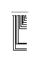
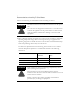
Motor Catalog Number Identification
FACTORY DESIGNATED OPTIONS
AA = Standard
AN = NEMA Mounting Flange/Shaft
BRAKE
2 = No Brake
4 = 24VDC Brake
CONNECTORS
3 = Flying Leads with Connectors
ENCLOSURE/SHAFT KEY/SHAFT SEA L
J = IP65 Housing/Shaft Key/No Shaft Seal
K = IP65 Housing/No Shaft Key/No Shaft Seal
FEEDBACK
B = Absolute Encoder, Battery-backed Multi-turn
H = Incremental Encoder (2000 lines)
RATED SPEED
A = 500 rpm
B = 1000 rpm
C = 1500 rpm
D = 2000 rpm
E = 2500 rpm
F = 3000 rpm
G = 3250 rpm
H = 3500 rpm
J = 3750 rpm
K = 4000 rpm
L = 4250 rpm
M = 4500 rpm
N = 4750 rpm
P = 5000 rpm
Q = 5250 rpm
R = 5500 rpm
S = 5750 rpm
T = 6000 rpm
MAGNET STACK LENGTH DESIGNATOR
FLANGE SIZE
Diameter of Mounti ng Bolt Circle for Metr ic Motor s, or NEMA size
1 = 46 mm or NEMA 17
2 = 70 mm or NEMA 23
25 = 90 mm or NEMA 34
3 = 100 mm
4 = 115 mm
VOLTAGE RATING
A = 230 VAC
SERIES DESIGNATOR
TL = Low Inertia
TL - A 4 10 M - B J 3 2 AA