
User Manual

TL-Series Servo Motor Installation Instructions 13
Publication TL-IN001C-EN-P — March 2005
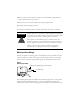
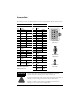
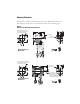
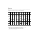
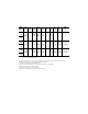
Connector Data
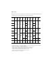
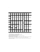
This table provides signal descriptions for the flying leads on all TL-Series motors.
Absolute Encoder Incremental Encoder
Feedback Connector Feedback Connector Connector Housings
Pin Signal Pin Signal
1-6 Reserved — 1 A+ green
7 EPWR red 2 A- green/blk
8 ECOM and brown/blk 3 B+ blue
BAT- blk 4 B- blue/blk
9 SHIELD blk shrink 5 I+ yellow
10-11 Reserved — 6 S1 gray/blk
12 SD+ blue 7 +5V DC red
13 SD- blue/blk 8 ECOM black
14 BAT+ brown 9 SHIELD blk shrink
15 Reserved — 10 I- yellow/blk
Power Connector 11 S2 brown/blk
Pin Signal 12-14 Reserved —
1 U phase red 15 S3 white/blk
2 V phase white Power Connector
3 W phase black Pin Signal
4 Ground yellow/grn 1 U phase red
Brake Connector 2 V phase black
Pin Signal 3 W phase white
1 BR+ yellow 4 Ground yellow/grn
2BR-
-A410 only
blue
yellow
Brake Connector
Pin Signal
See page 14 for additional
information about these
AMP™ connectors.
1BR+ yellow
2BR-
-A410 only
blue
yellow
!
ATTENTION
Ensure that cables are installed and restrained to prevent
uneven tension or flexing at the cable connectors.
Excessive and uneven force at the cable connector may result in
damage to the housing and contacts as the cable flexes.
Failure to observe these safety procedures could result in
damage to the motor and its components.
11
12
14
15
13
1
2
3
4
5
6
7
8
9
10
AMP HOUSING
P/N 172171-1
1
2
3
4
AMP HOUSING
P/N 350779-1
2
1
AMP HOUSING
P/N 172165-1