Installation Instructions TL-Series Servo Motor (Catalog Numbers TL-A110, -A120, -A130, -A220, -A230, -A2530, -A2540, A310, and -A410) This publication provides installation instructions for the TL-Series motors. Use this document if you are responsible for installing these Allen-Bradley® motor products. Please read all instructions before installing this motor.
TL-Series Servo Motor Installation Instructions Receiving and Storage The customer is responsible for inspecting the equipment before accepting the shipment from the freight company. Check the item(s) you receive against your purchase order. Notify the carrier of shipping damage or missing items immediately.
TL-Series Servo Motor Installation Instructions 3 Operating Temperature and Shaft Materials Condition or Material Description Operating Temperature 0° to 40° C (32° to 104° F) Shaft Material carbon steel Shaft Key Material carbon steel Publication TL-IN001C-EN-P — March 2005
TL-Series Servo Motor Installation Instructions Motor Catalog Number Identification TL - A 4 10 M - B J 3 2 AA FACTORY DESIGNATED OPTIONS AA = Standard AN = NEMA Mounting Flange/Shaft BRAKE 2 = No Brake 4 = 24VDC Brake CONNECTORS 3 = Flying Leads with Connectors ENCLOSURE/SHAFT KEY/SHAFT SEAL J = IP65 Housing/Shaft Key/No Shaft Seal K = IP65 Housing/No Shaft Key/No Shaft Seal FEEDBACK B = Absolute Encoder, Battery-backed Multi-turn H = Incremental Encoder (2000 lines) RATED SPEED A = 500 rpm B = 1000 rp
TL-Series Servo Motor Installation Instructions 5 Before You Install the Motor 1. Remove the motor carefully from its shipping container. 2. Visually inspect the motor for any damage. 3. Examine the motor frame, front output shaft, and mounting pilot for any defects. 4. Notify the carrier of any shipping damage immediately. ATTENTION ! Do not attempt to open and modify the motor. Modifications that can be performed in the field are described in this manual, other changes should not be attempted.
TL-Series Servo Motor Installation Instructions Prolonging Motor Life Thoughtful design and proper maintenance can increase the life of a servo motor. The following are guidelines to maximize the life of a servo motor. • Always provide a drip loop in each cable to carry liquids away from connections. • If design requirements permit, provide shields that protect the motor housing, shaft seals, and their junctions from product contamination and fluids.
TL-Series Servo Motor Installation Instructions 7 Making Mechanical Connection to the Motor Shaft Mechanical connections to the motor shaft, such as couplings and pulleys, require a torsionally rigid coupling or a reinforced timing belt. The high dynamic performance of servo motors can cause couplings, pulleys or belts to loosen or slip over time. A loose or slipping connection will cause system instability and may damage the motor shaft.
TL-Series Servo Motor Installation Instructions Installing Cables Knowledgeable cable routing improves system electromagnetic compatibility (EMC). To install the cables: 1. Keep wire lengths as short as physically possible. 2. Route signal cables (encoder, serial, analog, etc.) away from motor and power wiring. 3. Separate cables by 0.3 m (1 ft) minimum for every 9 m (30 ft) of parallel run. 4.
TL-Series Servo Motor Installation Instructions 9 • Ground all equipment using a single-point parallel ground system that employs ground bus bars or large straps. If necessary, use additional electrical noise reduction techniques to reduce EMI in noisy environments. Using Shaft Seals An additional seal is required on the motor shaft near the motor front bearing, if the shaft is exposed to fluids or significant amounts of fine dust.
TL-Series Servo Motor Installation Instructions Recommendations on Installing TL-Series Motors Observe the following recommendations when installing the motor. ATTENTION TL-Series motors are not for direct connection to an AC power line. ! Servo motors are designed for connection to a servo drive that controls the application of AC power. Failure to observe these safety procedures could result in damage to the motor and equipment. 1.
TL-Series Servo Motor Installation Instructions 11 2. Refer to Motor Load Force Ratings on page 11 to determine the radial and axial shaft load limitations of your motor. 3. Position the motor with the cable mounts pointing downward. 4. Properly mount and align the motor. 5. Connect the feedback, power, and brake cables after the motor is mounted.
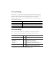
TL-Series Servo Motor Installation Instructions Radial Load Force Ratings Motor 1000 rpm 2000 rpm 3000 rpm 4500 rpm 5000 rpm kg (lb) kg (lb) kg (lb) kg (lb) kg (lb) 11 (24) 9 (19) 7 (16) – – 6 (14) TL-A120P 12 (26) 10 (21) 8 (18) – – 7 (15) TL-A130P 13 (29) 10 (23) 9 (20) – – 8 (17) TL-A110P TL-A220P 27 (60) 22 (48) 19 (42) – – 16 (35) TL-A230P 31 (68) 24 (54) 21 (47) – – 18 (40) TL-A2530P 48 (106) 38 (84) 34 (74) – – 28 (
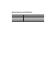
TL-Series Servo Motor Installation Instructions 13 Connector Data This table provides signal descriptions for the flying leads on all TL-Series motors.
TL-Series Servo Motor Installation Instructions Connector Type Feedback (15 Position) Brake (2 Position) Power (4 Position) 172171-1 172165-1 350779-1 Reel 770835-1 5 350218-3 10 Loose 794059-1 5 170359-1 7 170360-1 8 170363-1 7 170364-1 8 Motor Connectors (on flying leads): Plug Housing Power Contacts 1 Ground Contacts 2 Reel Loose — — 350547-3 10 350654-1 10 350669-1 10 Compatible Receptacles (on mating cables): Cap (receptacle) Housing 172163-1 172157-1 350780-1 Socket Contact
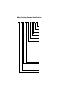
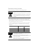
TL-Series Servo Motor Installation Instructions 15 Mounting Dimensions The dimension symbols and actual dimensions for the different frame sizes and stack lengths in the TL motors are referenced in tables on the following pages. Figure 2 References for Motor Mounting Dimensions Mounting pattern has two holes for A110 through A130 (shown). All others have four holes. L LB P N NB L-LB T TB Key (supplied) S dia. holes on M dia.
TL-Series Servo Motor Installation Instructions Metric Frame Dimensions are for non-brake motors. Footnotes provide additional dimensions for brake motors, and tolerances for common dimensions. Motor Series TL-A AD mm (in.) BE mm (in.) D1 mm (in.) HD mm (in.) 31.1 (1.22) 21.0 (0.83) 8.0 (0.315) 51.1 (2.01) 130 220 12.0 (0.472 4) 43.0 (1.69) 230 2530 L-LB 3 mm (in.) LA mm (in.) 53.0 (2.09) 27.6 (1.09) 16.0 (0.629 9) 2540 310 56.0 (2.20) 410 67.0 (2.64) 38.4 (1.51) 22.0 (0.
TL-Series Servo Motor Installation Instructions Motor Series TL-A N4 NB P S5 T TB mm (in.) mm (in.) mm (in.) mm (in.) mm (in.) mm (in.) 30.0 (1.1811) 20.0 (0.79) 40.0 (1.57) 4.5 (0.177) 2.5 (0.10) 4.5 (0.18) 50.0 (1.9685) 27.0 (1.06) 60.0 (2.36) 5.5 (0.217) CAB6 mm (in.) 17 G7 F8 Key 9 mm (in.) mm (in.) mm (in.) 110 120 3 x 3 x 15 6.2 3.0 (0.118 x 0.118 x (0.244) (0.118) 0.59) 130 220 300 (11.8) 230 2530 70.0 (2.7556) 2540 310 410 34.0 (1.34) 80.0 (3.15) 95.0 (3.
TL-Series Servo Motor Installation Instructions NEMA Frame Dimensions are for non-brake motors. Footnotes provide additional dimensions for brake motors, and tolerances for common dimensions. Motor Series TL-A 120 AC mm (in.) AD mm (in.) BE mm (in.) D1 mm (in.) HD mm (in.) L2 mm (in.) L-LB 3 mm (in.) 91.5 (3.603) 130 27.0 105.5 (1.063) (4.153) 220 137.9 (5.43) — 60 (2.36) 31.10 (1.22) 6.35 (0.25) 12.70 (0.50) 43.0 (1.69) 230 2530 21.0 (0.83) 52.0 (2.05) 73.0 (2.87) 27.
TL-Series Servo Motor Installation Instructions Motor Series TL-A 120 N4 NB P S5 T 19 G7 F8 Key 9 mm (in.) mm (in.) mm (in.) mm (in.) TB CAB 6 mm (in.) mm (in.) mm (in.) mm (in.) mm (in.) mm (in.) 22.0 (0.8661) — 42.0 (1.65) 8-32 Thread 2.0 (0.08) — 300 (11.8) — — — 38.1 (1.50) — 56.4 (2.22) 5.5 (0.217) 1.5 (0.06) — 300 (11.8) 10.92 (0.43) 3.175 (0.125) (0.125 x 0.125 x 0.9375) 73.02 (2.875) — 86.0 (3.39) 5.5 (0.217) 1.6 (0.06) — 300 (11.8) 13.13 4.763 (0.
TL-Series Servo Motor Installation Instructions Removing and Installing a Shaft Key TL shaft keys are constructed of carbon steel. Keys for metric mount motors are toleranced for interference fit (slightly larger than the opening) to ensure a secure and rigid fit for the mating connection. Keys for NEMA mount motors are toleranced for a slightly loose (slip) fit.
TL-Series Servo Motor Installation Instructions 21 Accessories Factory available accessories for the TL motors are described below. Motor Cables Factory manufactured feedback, brake, and power cables are available in standard cable lengths. Transition cables are available to allow connection of a TL-Series motor to existing N-Series or Y-Series power, feedback, and brake cables. Factory cables provide proper shield termination which reduces the potential for EMI.
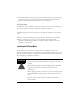
TL-Series Servo Motor Installation Instructions Transition Plates Transition plates allow a TL-Series NEMA motor to physically replace N-Series motors.
TL-Series Servo Motor Installation Instructions 23 Related Documentation These publications provide additional information; specifically about TL motors and compatible Rockwell Automation drives. To obtain a copy, contact your local Rockwell Automation office or distributor, or access the documents on-line at http://www.rockwellautomation.com/literature.
For more information refer to our web site: www.ab.com/motion For Rockwell Automation Technical Support information refer to: www.ab.com/support or Tel: (1) 440.646.5800 Allen-Bradley and Kinetix are registered trademarks of Rockwell Automation, Inc. Ultra1500 and Ultra3000 are registered trademarks of Rockwell Automation, Inc. AMP and TYCO are trademarks of Tyco International, Ltd.