
Instruction Manual

Publication TL-IN002A-EN-P — December 2004 P/N 9101-0465-001
Copyright © 2004 Rockwell Automation. All rights reserved. Printed in USA.
For more information refer to our web site: www.ab.com/motion
For Allen-Bradley Technical Support information refer to: www.support.rockwellautomation.com or Tel: (1) 440.646.5800
Allen-Bradley, and A-B are registered trademarks of Rockwell Automation.
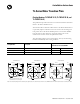
Installation Instructions
To attach an transition plate to a TL-Series NEMA motor:
1. Align the mounting holes in the transition plate with those in the
TL-Series NEMA motor.
2. Insert the mounting screws from the proper direction, and then torque
each screw to the appropriate value.
• TL-TRPLAT-17-23 requires two screws through the face of the
transition plate and into the front of the motor mount.
• TL-TRPLAT-23-34 and TL-TRPLAT-34-42 require four screws
through the back of the motor mount and into the rear of the
transition plate.
Refer to the TL-Series Servo Motor Installation Instructions (publication
TL-IN001x-EN-P) for detailed information on mounting, maintaining, and
troubleshooting a TL-Series NEMA motor. To obtain a copy, contact your
local Rockwell Automation office or distributor, or access the document
on-line at http://
www.rockwellautomation.com
/literature.
ATTENTION
!
Energy may be stored in a drive system after power is
removed.
Before disconnecting mechanical or electrical connections
to a motor, remove power from the drive system and allow
the bus capacitance to discharge for the time indicated on
the front of the drive.
Failure to observe safety procedures could result in personal
injury or equipment damage.
Catalog Number of Transition Plate Mounting Hardware Torque Requirements
TL-TRPLAT-17-23 Two 8-32 cap screws 3.0 - 3.7 Nm (27 - 33 lb-in.)
TL-TRPLAT-23-34
Four 10-32 cap screws 6.1 - 7.5 Nm (54 - 66 lb-in.)
TL-TRPLAT-34-42