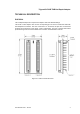
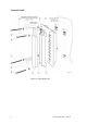
Triguard SC300E THR Hot Repair Adaptor (THR) Issue 6 October 2005 INTRODUCTION PURPOSE The Hot Repair Adaptor kit enables the backplane field connectors of two adjacent I/O modules to be bridged so that both are connected to a single set of field connections in a Dual Hot Repair configuration. The kit comprises two Hot Repair Adaptor cards and the appropriate hardware fittings. The assembly and fitting of one adaptor card to the chassis backplane is shown in Figure 3-1.
Triguard SC300E ENVIRONMENTAL SPECIFICATIONS The maximum ambient temperature measured at the hottest point within the Triguard system shall not be greater than 60 degrees centigrade. Temperature operating: +5°C to +60°C Temperature storage: -25°C to +70°C Humidity 5% to 95% non-condensing at ambient <40°C EMC/RFI Immunity Tested and certified to IEC 1131-Part 2 1994 Vibration/Shock Tested and certified to IEC 1131-Part 2 1994 Certification: General Certification: Ref.
Triguard SC300E THR Hot Repair Adaptor TECHNICAL DESCRIPTION PHYSICAL The Hot Repair Adaptor kit comprises two adaptor cards and hardware fittings The tracks in each adaptor card connect corresponding pins of the two sockets that mate with the backplane connectors. The rear of Connector ‘A’ is unused, the pins are cut short and protected by the shell and cover (items 7 and 6 respectively). The pins of the left hand socket protrude through a shroud which enables the connection of the field DIN connector.
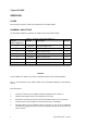
Triguard SC300E SERVICING SCOPE No servicing is necessary, repair is by replacement of the faulty adaptor. ASSEMBLY AND FITTING The Hot Repair Adaptor kit comprises two adaptor cards and hardware fittings. Table 3-1. Contents of Hot Repair Adaptor kit Item No Part No. Description No. off (refer to Figure 3-1) 1 099-1245 Hot repair adaptor card 2 2 600-1079 M3 x 3mm spacer 4 3 525-7625 M2.5 x 25mm screw 4 4 507-0175 M2.5 x spring washer 8 5 525-7619 M2.
Triguard SC300E THR Hot Repair Adaptor 6. Attempt to fully engage the adaptor card but if excessive resistance is felt remove the card and check for bent pins or any other obstructions. 7. Using items 2, 3 and 4 fit one of the shrouds to the card over the pins of the left hand connector; ensure that the shroud is correctly oriented (keys on the left, Figure 3-1. ). Note that the two spacers (item 2) fit between the shroud and the card. Do not over tighten the screws. 8.
Triguard SC300E Figure 3-1.
Triguard SC300E THR Hot Repair Adaptor SERVICE SUPPORT SPARE PARTS Spare parts and technical advice can be obtained from your local area offices.