
Manual
TDO16AIN
October
200
5
–
Issue 6
7
Triguard
SC300E TDO16AIN 16
-
Channel D/O Termination Card 24Vdc
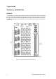
THEORY OF OPERATION
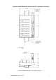
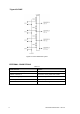
Figure
2
-
4 shows
a circuit
diagram
of
a typical
digital
output
channel.
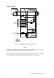
Power
supplies
for
the
termination
cards
are
normally
provided
by
a Power
Distribution
Panel
PDD24.
Power
for
th
e digital
output
channels
is
distributed
as
shown
in
Figure
2
-
3 . Soldered
links
LK1
to
LK4
are
normally
present,
and
in
low
load
applications,
external
power
can
be
connected
to
any
one
of
the
four
inputs
FS1
to
FS4.
For
high
load
applications,
or
where
t
he
channel
groups
require
different
supply
voltages,
cut
the
links
and
supply
FS1
to
FS4
individually.
Each
digital
output
channel
is
powered
from
a common
+ve
bus.
An
indicating
fuse
is
fitted
in
the
digital
output
signal
line
to
the
field
device.
The
‘fuse
failed’
output
from
each
fuse
is
connected
to
a common
alarm
bus.
If
any
fuse
fails,
local
indication
is
provided
by
the
illumination
of
the
Fuse
blown
LED
LD1.
A signal
to
operate
a remote
alarm
is
available
at
Alarm
output
PL1.
The
-
ve
bus
may
be
gr
ounded
via
TS1
if
required,
preventing
the
power
supplies
from
‘floating’
when
the
chassis
cable
is
disconnected.