Triguard SC300E TDO16AIN 16-Channel Digital Output Termination Card Introduced Power 24Vdc (TDO16AIN) Issue 6 October 2005 INTRODUCTION PURPOSE The TDO16AIN 16-channel digital output termination card acts as an interface between the digital output circuits of an SC300E chassis and the field devices which they control.
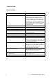
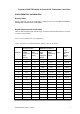
Triguard SC300E SPECIFICATION Model TDO16AIN Power supply inputs Has four separate connectors (FS1, FS2, FS3 and FS4) for dc power supplies. The four positive supplies feed individual sections of the digital outputs via common buses. The buses are linked together. For lightly loaded applications (e.g. 6A) all the required power can be supplied via one connector. For highly loaded applications (e.g. 16A) use multiple power connectors. No.
Triguard SC300E TDO16AIN 16-Channel D/O Termination Card 24Vdc ENVIRONMENTAL SPECIFICATIONS The maximum ambient temperature measured at the hottest point within the Triguard system shall not be greater than 60 degrees centigrade.
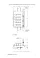
Triguard SC300E TECHNICAL DESCRIPTION PHYSICAL The TDO16AIN comprises a PCB assembly mounted in a moulded carrier that can be snapped onto all commercially available styles of DIN EN mounting rail. Connection to the chassis backplane is via a multicore cable terminated at either end by a DIN41612 connector. Figure 22 shows the TDO16AIN with the DIN41612 connector attached and mounted on rail EN 50022 type NS 35/5.
Triguard SC300E TDO16AIN 16-Channel D/O Termination Card 24Vdc Figure 2-2 Leading dimensions and mounting schematic TDO16AIN October 2005 – Issue 6 5
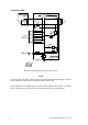
Triguard SC300E Figure 2-3 Power distribution system EXTERNAL CONNECTIONS Table 2-1. 6 Fixed terminal Details Field terminals 1 to 16 (+) Screw terminal to suit 2.
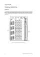
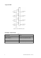
Triguard SC300E TDO16AIN 16-Channel D/O Termination Card 24Vdc THEORY OF OPERATION Figure 2-4 shows a circuit diagram of a typical digital output channel. Power supplies for the termination cards are normally provided by a Power Distribution Panel PDD24. Power for the digital output channels is distributed as shown in Figure 2-3 . Soldered links LK1 to LK4 are normally present, and in low load applications, external power can be connected to any one of the four inputs FS1 to FS4.
Triguard SC300E Figure 2-4 Circuit diagram showing a single channel NOTE Current for alarm indication is taken from the chassis module digital output signal. An alarm will be signalled only when the fuse has failed and this output is high. Power distribution panel PDD24 has a Fuse blown alarm indicator with provision for multiple inputs. This facility can be wired to provide fuse blown indication for an entire cabinet.
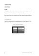
Triguard SC300E TDO16AIN 16-Channel D/O Termination Card 24Vdc SUPPLEMENTARY INFORMATION Dummy loads Dummy loads are only to be connected to outputs that are not used. Do not connect a dummy load in parallel with a real output. Digital output channel connections Table 2-2 lists the digital output channel wiring connections and associated fuses for connector J1 and the screw terminals. Pin J1-1a is connected to the -ve bus (Figure 2-4 ).
Triguard SC300E SERVICING SCOPE The TDO16AIN contains all-passive circuitry that is extremely robust. Servicing operations will therefore not normally extend beyond the replacement of blown fuses. CAUTION Before replacing a blown fuse, ascertain the cause of failure, and take the appropriate remedial action. CONFIGURATION Links LK1 to LK4 are connected by default (see Figure 2-3 ).
Triguard SC300E TDO16AIN 16-Channel D/O Termination Card 24Vdc SERVICE SUPPORT SPARE PARTS Spare parts and technical advice can be obtained from your local area offices.