
Owner manual

TDI16BIA
October
200
5
–
Issue 3
7
Triguard
SC300E TDI
16BIA
16
-
Channel D/I Termination Card 24Vdc
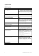
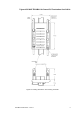
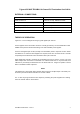
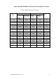
EXTERNAL
CONNECTIONS
Fixed
Terminal
Details
Field
connector
J2
Connector,
34
-
way,
DIN41612,
female
Chassis
connector
J1
Connector
,
34
-
way,
DIN41612,
female
Field
power
supply
inputs
FS1
and
FS2
Header,
2
-
way,
Molex
Minifit
Jr
Alarm
output
PL1
Header,
2
-
way,
Molex
KK
Ground
terminal
TS1
Provision
for
M3
ring
terminal
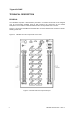
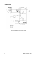
THEORY OF OPERATION
Figure
2
-
3 is
a circuit
diagram
showing
a typical
digital
input
channel.
Power
supplies
for
the
termination
cards
are
normally
provided
by
a Power
Distribution
Panel
PDD24
which
performs
diode
auctioneering
of
its
dual
redundant
power
supplies.
Power
for
the
digital
input
circuits
(normally
from
the
PDD24)
is
fed
to
input
FS1
or
FS2.
Where
the
PDD24
is
not
used
and
dual
supplies
are
required,
these
are
connected
to
FS1
and
FS2
respectively
and
auctioneered
on
the
termination
card
by
D17
and
D18.
Each
digital
input
channel
is
powered
via
an
indicating
fuse
from
a common
+ve
bus.
The
‘fuse
failed’
output
from
each
fuse
is
connected
to
a common
alarm
bus.
If
any
fuse
fails,
local
indication
is
pr
ovided
by
the
illumination
of
Fuse
blown
LED
LD1.
A signal
to
operate
a remote
alarm
is
available
at
Alarm
output
PL1.
NOTE
The
PDD24
has
a Fuse
blown
alarm
indicator
with
provision
for
multiple
inputs.
This
facility
can
be
wired
to
provide
fuse
blown
indication
for
an
entire
cabinet.
The
-
ve
bus
may
be
grounded
via
TS1
if
required,
preventing
the
power
supplies
from
‘floating’
when
the
chassis
cable
is
disconnected.